Quantcast
Viewing all 370 articles
Browse latest View live

Cloudstats.me – The Next-Gen Server Monitoring Platform

Cloudstats.me  is the Next-Gen server/website monitoring platform which suits for  Linux, windows servers and enterprise websites. I have been worked with several enterprise monitoring tools but Cloudstats stands out with it’s simplicity. You no need to spend thousands of dollors to  buy the monitoring software and hire the resources to setup the  monitoring services platform.  Also you no need to spend single penny for the hardwares and datacenter space. Cloudstats provides world’s most simple and effective monitoring platform where your systems are monitored in the cloud in few clicks. In this article, we will see that how  we can setup the Cloudstats monitoring for Rehdat Enterprise Linux 7/Cent OS .

CloudStats also has a completely free account for those who plan to monitor 3 servers or less servers.

Use the below link to sign-up in the cloudstats.me . Its completely free to monitor to to three servers or websites. Your system must have internet access to get connected with cloudstats.

http://login.cloudstats.me/referrals?ref=1391

Features of Cloudstats.me:

  • Linux and Windows Server Monitoring.
  • It Supports CentOS, Debian, Ubuntu and Windows servers.
  • Support of VPS, Dedicated and Cloud servers.
  • Simple agent installation.
  • Website Monitoring and Pingmap.
  • Service monitoring (FTP, DNS, SSH, MAIL, DNS, HTTP etc.. )
  • Port monitoring (22, 80, 443 etc.)
  • All in one Dashboard.
  • Powerful charts.
  • Suitable for small to mid-range servers environment.
  • Configurable EMAIL, Skype Alerts.
  • Free Server UP/Down Alerts.
  • No load for your system since its lightweight.

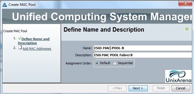
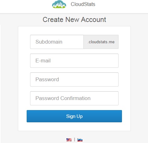
1. Sign-up in Cloudstats.me. “Subdomain” name could be anything.  You can also keep your organization or website name. Here I have just used my name.

Image may be NSFW.
Clik here to view.
Sign-up for free
Sign-up for free


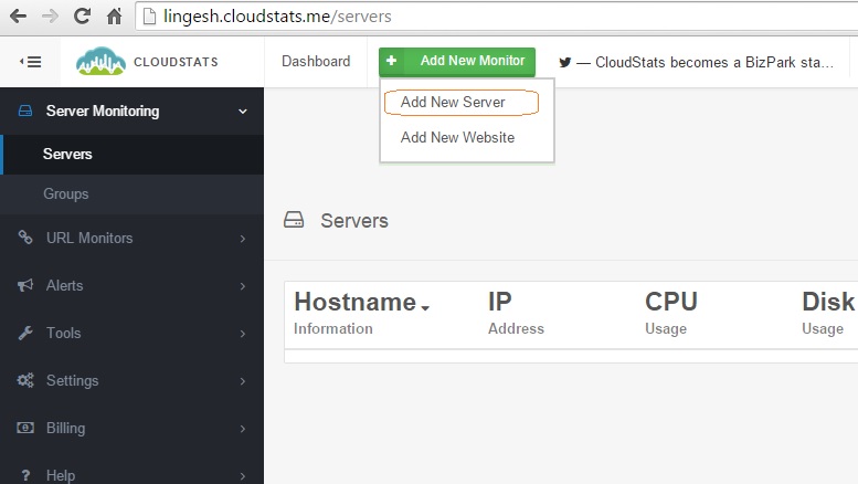
2. Once you sign-up , you will be re-directed to dashboard.  Click on “Add New Monitor” and Select “Add New Server” .

Image may be NSFW.
Clik here to view.
Cloudstat - Add Server
Cloudstats – Add Server


3. Choose the operating system type. Here I am choosing Linux.

Image may be NSFW.
Clik here to view.
Select the OS type
Select the OS type


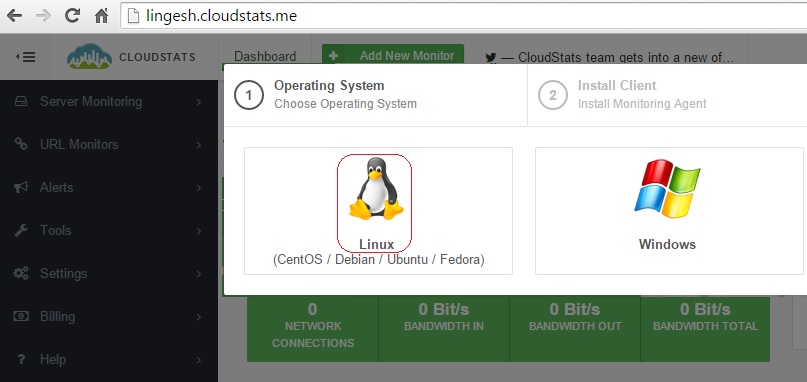
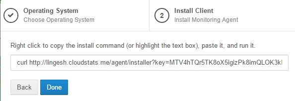
4. You will get the below screen once you have select the OS type.  Copy the URL .

Image may be NSFW.
Clik here to view.
CURL URL
CURL URL


5. Login to the Linux server which you would like to add it in the cloudstats monitoring.

login as: root
root@192.168.203.141's password:
Last login: Wed Jun 24 09:24:26 2015
[root@RHEL7 ~]#
[root@RHEL7 ~]#

Note: You must login as a root.


6.  Paste the curl URL which you have copied in the step 4.

[root@RHEL7 ~]# curl http://lingesh.cloudstats.me/agent/installer?key=MTV4hTQr5TK8oX5igizPk8imQLOK3kI6P5ISqm5pbFkTr5c9Q6d6655mebCOJvrJJ | sh
  % Total    % Received % Xferd  Average Speed   Time    Time     Time  Current
                                 Dload  Upload   Total   Spent    Left  Speed
100  1518  100  1518    0     0   1362      0  0:00:01  0:00:01 --:--:--  1365
CloudStats agent will be installed in:
/home/cloudstats_agent

Downloading cloudstats.py ...
Setting permissions on cloudstats.py ...
Downloading cloudstats_core.py ...
Downloading cloudstats_services.py ...
Installing CRON entry ...
Running first time ...
which: no aptitude in (/usr/local/sbin:/usr/local/bin:/sbin:/bin:/usr/sbin:/usr/bin:/root/bin)
Status posted to https://lingesh.cloudstats.me/status/update?key=MTV4hTQr5TK8oX5igizPk8imQLOK3kI6P5ISqm5pbFkTr5c9Q6d6655mebCOJvrJJ
Server updated
Installation finished.
[root@RHEL7 ~]#


7. Once the installation is completed, you can see that cloudstats process is started.

[root@RHEL7 ~]# ps -ef |grep cloud
root     30696 30694  0 09:28 ?        00:00:00 /bin/bash -c /home/cloudstats_agent/cloudstats.py >/dev/null 2>&1
root     30698 30696  0 09:28 ?        00:00:00 python /home/cloudstats_agent/cloudstats.py
root     30749 30483  0 09:28 pts/1    00:00:00 grep --color=auto cloud
[root@RHEL7 ~]# cd /home/
[root@RHEL7 home]#


8. The automated cloudstats installation will made the entry in the system crontab as well to report the statistics to cloudstats server for every four minutes.

[root@RHEL7 ~]# cat /etc/crontab
SHELL=/bin/bash
PATH=/sbin:/bin:/usr/sbin:/usr/bin
MAILTO=root

# For details see man 4 crontabs
# Example of job definition:
# .---------------- minute (0 - 59)
# |  .------------- hour (0 - 23)
# |  |  .---------- day of month (1 - 31)
# |  |  |  .------- month (1 - 12) OR jan,feb,mar,apr ...
# |  |  |  |  .---- day of week (0 - 6) (Sunday=0 or 7) OR sun,mon,tue,wed,thu,fri,sat
# |  |  |  |  |
# *  *  *  *  * user-name  command to be executed

*/4 * * * * root /home/cloudstats_agent/cloudstats.py >/dev/null 2>&1
[root@RHEL7 ~]#


9. Let me go back to the cloudstats.me portal .

In the dashboard ,you can see that server has been added in the  cloudstats monitoring.

Image may be NSFW.
Clik here to view.
Cloudstat - Dashboard
Cloudstats – Dashboard


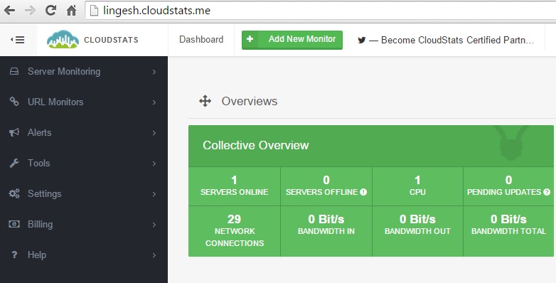
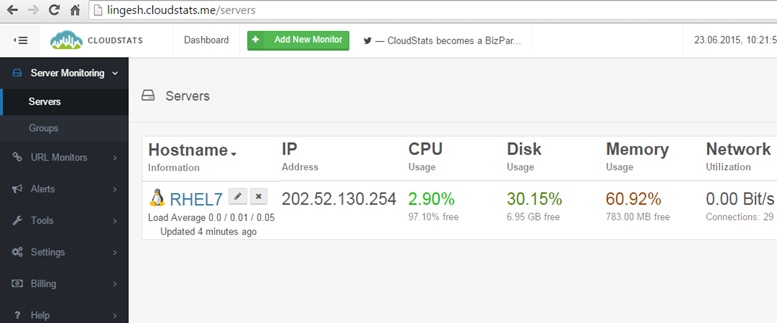
10.  Click on the “SERVES ONLINE” tab which shows in the above screenshot. This  will shows the servers resource utilization like below.

Image may be NSFW.
Clik here to view.
Resource utilization Details


11. Click on the “Alerts” tab to configure the customized alerts.  Click on “Create Alert” tab.

Image may be NSFW.
Clik here to view.
Create the New Alert


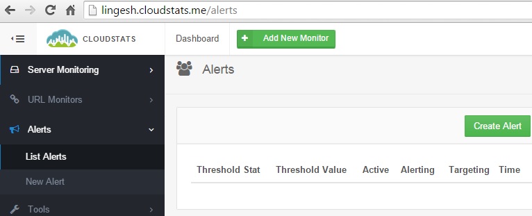
12. In  this screen, you need to choose the pre-defined alerts type and specify the threshold value.

Image may be NSFW.
Clik here to view.
Specify the alert type and set the thersold


In this threshold tab, i have specified as 30 for testing purpose. Normally that will be 90%.


13. Once the alert has been created, cloudstats agent will monitor the specific parameter what we have defined in the previous step. According to that it will create a notification if needed.

Example:

Image may be NSFW.
Clik here to view.
Alert - sample
Alert – sample


Unless you fix the issue , cloudstats will be keep on triggering the alert.

Image may be NSFW.
Clik here to view.
Cloudstat will never give-up
Cloudstats will never give-up


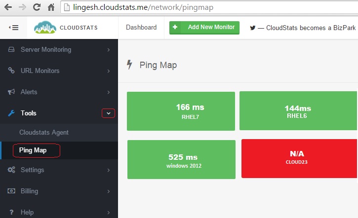
14.  PingMap allows you to quickly see which of your servers are UP/Down . Here you can see host cloud23 is down or not reachable. The other three hosts are available.

Image may be NSFW.
Clik here to view.
Pingmap
PingMap


15. Cloudstats can provide a wonderful graph based statistics for each hosts. You can see the server statistics by navigating to “Server Monitoring”  tab- > Click on the “host”.

Image may be NSFW.
Clik here to view.
CPU
Image may be NSFW.
Clik here to view.
Memory
Image may be NSFW.
Clik here to view.
Disk Usage
Image may be NSFW.
Clik here to view.
Network Bandwidth
Image may be NSFW.
Clik here to view.
IO Usage
Image may be NSFW.
Clik here to view.
Loads

Click on the above screenshot to see image in full size. 

Hope this article is informative to you. Share it ! Be Sociable !!!

The post Cloudstats.me – The Next-Gen Server Monitoring Platform appeared first on UnixArena.


How to Measure the bandwidth between Linux / Solaris hosts ?

All the new servers are shipping with 10 Gbps built-in network adapters .  At the same time, servers are virtualized and one physical server may hosts many virtual servers. For an example, VMware ESXi hypervisor will be directly installed on physical server and multiple VM’s will be created on top of that. So all the VM’s will share the same 10Gbps network interface. That’s why throughput will not be always 10 Gbps between the VM’s and other network even though your VM host shows as network connected with 10Gbps. In this article , we will see the real time TCP network bandwidth between VM hosts using iperf utility.  The VM hosts can be a Linux , windows or Solaris servers. Iperf works in server/client model to measure the network bandwidth.

iperf utility can be downloaded from iperf.fr.  Here is pre-complied binaries for various server operating systems.

Image may be NSFW.
Clik here to view.
Windows
Iperf for Windows 2000, XP, 2003, Vista, 7, 8 and Windows 10 :

  • Iperf 2.0.5-3 (1421 Kio) – The latest version of Iperf 2 (2014).

Image may be NSFW.
Clik here to view.
Linux x86 32 bits
Iperf for Linux x86 32 bits (i386) :

Image may be NSFW.
Clik here to view.
Linux x86 64 bits
Iperf for Linux x86 64 bits (AMD64) :

Image may be NSFW.
Clik here to view.
MacOS X
Iperf for MacOS X :

Image may be NSFW.
Clik here to view.
Solaris
Iperf for Oracle Solaris :

  • Iperf 2.0.4 for Solaris 10 x86 (62 Ko) SPARC (62 Ko)
  • Iperf 2.0.4 for Solaris 9 x86 (61 Ko) SPARC (62 Ko)
  • Iperf 2.0.4 for Solaris 8 x86 (61 Ko) SPARC (64 Ko)


Iperf  Installation on Oracle Solaris 9/10


1.  Copy the Iperf package to Solaris 10 host.

2. Login to the Solaris 10 host. Un-zip the package and install it using pkgadd.

[root@SOL10:/var/tmp]# ls -lrt
-rw-r--r--   1 root       63116 Jun 18 11:26 iperf_2.0.4_solaris10_x86.gz
[root@SOL10:/var/tmp]$ gunzip iperf_2.0.4_solaris10_x86.gz
[root@SOL10:/var/tmp]# ls -lrt
-rw-r--r--   1 root   163328 Jun 10 10:59 iperf_2.0.4_solaris10_x86
[root@SOL10:/var/tmp]$ file iperf_2.0.4_solaris10_x86
iperf_2.0.4_solaris10_x86:      package datastream
[root@SOL10:/var/tmp]$ pkgadd -d /var/tmp/iperf_2.0.4_solaris10_x86

The following packages are available:
  1  SMCiperf     iperf
                  (x86) 2.0.4

Select package(s) you wish to process (or 'all' to process
all packages). (default: all) [?,??,q]:

Processing package instance  from 

iperf(x86) 2.0.4
Mark Gates, Alex Warshavsky, et al
Using  as the package base directory.
## Processing package information.
## Processing system information.
   5 package pathnames are already properly installed.
## Verifying disk space requirements.
## Checking for conflicts with packages already installed.
## Checking for setuid/setgid programs.

Installing iperf as 

## Installing part 1 of 1.
/usr/local/bin/iperf
/usr/local/doc/iperf/AUTHORS
/usr/local/doc/iperf/COPYING
/usr/local/doc/iperf/ChangeLog
/usr/local/doc/iperf/INSTALL
/usr/local/doc/iperf/README
/usr/local/doc/iperf/doc/Makefile
/usr/local/doc/iperf/doc/Makefile.am
/usr/local/doc/iperf/doc/Makefile.in
/usr/local/doc/iperf/doc/dast.gif
/usr/local/doc/iperf/doc/index.html
/usr/local/doc/iperf/doc/ui_license.html
/usr/local/share/man/man1/iperf.1
[ verifying class  ]

Installation of  was successful.
[root@SOL10:/var/tmp]$

Here the options of iperf.

[root@SOL10:/var/tmp]$ /usr/local/bin/iperf --help
Usage: iperf [-s|-c host] [options]
       iperf [-h|--help] [-v|--version]

Client/Server:
  -f, --format    [kmKM]   format to report: Kbits, Mbits, KBytes, MBytes
  -i, --interval  #        seconds between periodic bandwidth reports
  -l, --len       #[KM]    length of buffer to read or write (default 8 KB)
  -m, --print_mss          print TCP maximum segment size (MTU - TCP/IP header)
  -o, --output     output the report or error message to this specified file
  -p, --port      #        server port to listen on/connect to
  -u, --udp                use UDP rather than TCP
  -w, --window    #[KM]    TCP window size (socket buffer size)
  -B, --bind         bind to , an interface or multicast address
  -C, --compatibility      for use with older versions does not sent extra msgs
  -M, --mss       #        set TCP maximum segment size (MTU - 40 bytes)
  -N, --nodelay            set TCP no delay, disabling Nagle's Algorithm
  -V, --IPv6Version        Set the domain to IPv6

Server specific:
  -s, --server             run in server mode
  -U, --single_udp         run in single threaded UDP mode
  -D, --daemon             run the server as a daemon

Client specific:
  -b, --bandwidth #[KM]    for UDP, bandwidth to send at in bits/sec
                           (default 1 Mbit/sec, implies -u)
  -c, --client       run in client mode, connecting to 
  -d, --dualtest           Do a bidirectional test simultaneously
  -n, --num       #[KM]    number of bytes to transmit (instead of -t)
  -r, --tradeoff           Do a bidirectional test individually
  -t, --time      #        time in seconds to transmit for (default 10 secs)
  -F, --fileinput    input the data to be transmitted from a file
  -I, --stdin              input the data to be transmitted from stdin
  -L, --listenport #       port to recieve bidirectional tests back on
  -P, --parallel  #        number of parallel client threads to run
  -T, --ttl       #        time-to-live, for multicast (default 1)
  -Z, --linux-congestion   set TCP congestion control algorithm (Linux only)

Miscellaneous:
  -x, --reportexclude [CDMSV]   exclude C(connection) D(data) M(multicast) S(settings) V(server) reports
  -y, --reportstyle C      report as a Comma-Separated Values
  -h, --help               print this message and quit
  -v, --version            print version information and quit

[KM] Indicates options that support a K or M suffix for kilo- or mega-

The TCP window size option can be set by the environment variable
TCP_WINDOW_SIZE. Most other options can be set by an environment variable
IPERF_, such as IPERF_BANDWIDTH.

Report bugs to <iperf-users@lists.sourceforge.net>

#


Iperf  installation on Redhat Enterprise Linux 5.x/6.x/7.x


Iperf RPM package is available in RHEL DVD itself. Copy the iperf package to Redhat Linux server.

1. Login to the server and install the package using rpm command.

[root@RHEL5 tmp]# rpm -ivh iperf-2.0.4-1.el5.rf.x86_64.rpm
warning: iperf-2.0.4-1.el5.rf.x86_64.rpm: Header V3 DSA signature: NOKEY, key ID 6b8d79e6
Preparing...                ########################################### [100%]
   1:iperf                  ########################################### [100%]
[root@RHEL5 tmp]#

If your server is configured with yum repository , you can use the “yum install iperf* ”  command.


How to Measure the bandwidth between the two VM’s ?


Here we are going to measure bandwidth between servers SOL10 (192.168.2.34) & RHEL5 (192.168.2.40).
1.  Login to SOL10 host where iperf is already installed.(Source)

2.  Execute Iperf in a server mode. Keep the session live.

[root@SOL10:/root]$ iperf -f M -p 8000 -s -m
------------------------------------------------------------
Server listening on TCP port 8000
TCP window size: 0.05 MByte (default)
------------------------------------------------------------

3.  Login to RHEL5 host and execute the iperf with destination IP. (Destination)

[root@RHEL5 ~]# iperf -c  192.168.2.34  -p 8000 -t 60
------------------------------------------------------------
Client connecting to 192.168.2.34, TCP port 8000
TCP window size: 16.0 KByte (default)
------------------------------------------------------------
[  3] local 192.168.2.40 port 50393 connected with 192.168.2.34 port 8000
[ ID]   Interval      Transfer        Bandwidth
[  3]  0.0-60.0 sec   6.57 GBytes    941 Mbits/sec
[root@RHEL5 ~]#

– t 60 – Seconds
– p 8000 – Default port used to connect to iperf.
– c 192.168.2.34 – Server IP

After 60 seconds test, will get the results like above. This results will be shown in Megabits per seconds

4.  Go back to SOL10 console and see the results. It will be shown in Megabytes per second.

[root@SOL10:/root]$ iperf -f M -p 8000 -s -m
------------------------------------------------------------
Server listening on TCP port 8000
TCP window size: 0.05 MByte (default)
------------------------------------------------------------
[  4] local 192.168.2.34 port 8000 connected with 192.168.2.40 port 18263
[ ID] Interval       Transfer     Bandwidth
[  4]  0.0-60.0 sec  6707 MBytes    112 MBytes/sec
[  4] MSS size 1448 bytes (MTU 1500 bytes, ethernet)
^C[root@SOL10:/root]$


The same way you can measure the real bandwidth between any type of VM’s or physical hosts.  At this time, iperf supports only Solaris , Linux and Windows operating systems.

Hope this article informative to you .

The post How to Measure the bandwidth between Linux / Solaris hosts ? appeared first on UnixArena.

Cisco UCS B-Series – UCS Manager Overview – Part 5

The computer industry is on the major transition due to the server consolidation and virtualization products on the market. Cisco is commonly known for networking  components like switches, routers and IP phones. But in 2009 , they have entered in to the X86 server market on their own style with data centre virtualization and consolidation methods.

There was a small history behind the Cisco UCS X86 servers.

  • In 2008, VMware made a  partnership with Cisco and the outcome was  Cisco  Nexus 1000V, a distributed virtual software switch which can be integrated with VMware vpShere.
  • In 2009 , IBM, HP and Dell hardware vendors were leading in the blade servers market.
  • At the same time , VMware also started capturing the server market with rock solid virtualization products.
  • Cisco have proposed to IBM , Dell and HP to bring the blade server’s control plane to the Cisco UCS  Manager  to integrate the more networking features to the blades. This is nothing but managing the whole blade chassis from UCS manager.But they didn’t accept it.
  • So Cisco has released their own X86 servers in the market with the brand name of Cisco Unified Computing System (UCS) in 2009.
  • As a result of Cisco UCS  success, DELL and HP  are trying to do that what Cisco has done 5 years back.

What Cisco has done differently with UCS B-Servers blade servers ?

In HP,IBM and Dell blade servers are managed from chassis. But here the case is different . Cisco brought the control plane(L2 Layer) completely out from the chassis. The blade and chassis are managed by the Fabric interconnect which is nothing but a UCS manager.

Cisco UCS – B – Series Topology:

Image may be NSFW.
Clik here to view.
Cisco UCS B-series Topology


The below image shows the Cisco UCS chassis of back side & Front side.

Image may be NSFW.
Clik here to view.
Cisco UCS - B Series
Cisco UCS – B Series


1. FEX (Fabric Extended Module )or IOM (Inout/Output Module):

FEX extends the I/O fabric between the Cisco UCS  Fabric Interconnects and the Cisco UCS  B-Series Blade Server Chassis. The fabric extender is like a distributed line card, it does not perform any switching and is managed as an extension of the fabric interconnects. FEX manages the entire chassis  which includes the blades, fans and power supply with help of Fabric interconnect. So, separate chassis management modules are not required.

FEX second generation(Cisco UCS 2200  series) contains  8 x 10Gigabit up links ports (chassis to FI connectivity) and  it has thirty-two 10 Gigabit Ethernet ports connected through the midplane to each half-width slot in the chassis. Normally ,we will be configuring the FEX with pairs of redundancy. So it can provide up to 160 Gbps I/O to Chassis. (8x10Gbps + 8x10Gbps = 160Gbps.)


Per Half Blade = 1 x 10Gbps (FEX 1) + 1x10Gbps (FEX 2) = 20Gbps of LAN/SAN traffic.

Full Blade = 2 x 10Gbps (FEX 1) + 2x10Gbps (FEX 2) = 40Gbps of LAN/SAN traffic.

Blades are connected internally with FEX in the chassis. So there is no cabling required between blades and FEX.


2. What is Fabric Interconnect (FI) ?

The Fabric interconnect is the heart of Cisco UCS systems. FI is provides the LAN/SAN Connectivity, Management to the chassis. In traditional blade systems , LAN & SAN network will be going to its pear part directly from chassis. Since all the Cisco blades are using mezzanine cards, both SAN & LAN traffic will be carried in to single medium till Fabric interconnect.  From there traffic will be routed to its pear. FI runs on NX-OS and its nothing but a Nexus switch. UCS manager is the software which is installed on Fabric interconnect to manage the whole UCS infrastructure.

Image may be NSFW.
Clik here to view.
CISCO FI (UCS MANAGER)


3.  Do  you would like to know that how the mezzanine card works ? Please Check out here.

We have seen the different components which are used in the Cisco B-series computing.  Hope you got a better idea about it . In the upcoming article, we will see that how to discover the chassis from the UCS manager (FI)

Thank you for visiting UnixArena.

The post Cisco UCS B-Series – UCS Manager Overview – Part 5 appeared first on UnixArena.

Setup the Cisco UCS environment and configure the UCS ?

This article will provide the step by step instructions to setup the Cisco UCS environment for first time. Cisco UCS is highly customizable and  the configuration will be differ for each environment. The core part of  Cisco UCS deployment is  cabling. Unlike the traditional chassis , Cisco UCS have additional components like I/O modules (FEX) and Fabric interconnects (FI / UCS Manager). Fabric interconnect has its own management ports to manage it. There will be a dedicated ports to provide the connectivity between FI’s. So that both the FI’s configuration will be sync with each other.

1. Setup  the Fabric Interconnect (UCS Manager) . You need to interconnect the FI’s to make the FI cluster.

Image may be NSFW.
Clik here to view.
FI interconnects
FI interconnects

The Fabric interconnect’s MGMT port needs to be connected to the management network. Connect the L1 port of Fabric Interconnect “A” to the L1 port of fabric interconnect “B”.  Do likewise for the L2 ports. L1 & L2 ports are used for Fabric interconnect heart-beating and this connectivity ensures that both the FI’s maintaining the identical data.


2. Laid the cabling between the chassis and Fabric interconnect. So that chassis can be discovered in the UCS manager. L1 & L2 ports provides the connectivity between two FI’s.

Image may be NSFW.
Clik here to view.
Chassis to FI Cabling


3.  Connect the FI’s to the Nexus switch.  This Nexus switch has capability to diverging the LAN & SAN traffic to the peer devices.

Image may be NSFW.
Clik here to view.
UCS complete environment

At this point , you have physically setup the UCS environment.


4. Configuring the Fabric Interconnects.

Connect to the console port of Fabric Interconnect (FI) “A”, which will be the primary member of the cluster. Power on FI-A and leave the secondary FI off for now. Verify that the console port parameters on the attached computer are as follows “9600 baud”, “8 data bits”, “No parity”, “1 stop bit”. Once you have connected to the FI – A management console, you will get the interactive session like below.

Enter the configuration method. (console/gui) ? console
Enter the setup mode; setup newly or restore from backup. (setup/restore) ?
setup You have chosen to setup a new Fabric interconnect. Continue? (y/n): y
Enter the password for “admin”: password
Confirm the password for “admin”: password
Is this Fabric interconnect part of a cluster(select ‘no’ for standalone)? (yes/no) [n]: yes
Enter the switch fabric (A/B) []: A
Enter the system name: Fabric-DC1-A
Physical Switch Mgmt0 IPv4 address : X.X.X.X
Physical Switch Mgmt0 IPv4 netmask : X.X.X.X
IPv4 address of the default gateway : X.X.X.X
Cluster IPv4 address : X.X.X.X (NOTE: This IP address will be used for Management)
Configure the DNS Server IPv4 address? (yes/no) [n]: y
DNS IPv4 address : X.X.X.X
Configure the default domain name? (yes/no) [n]: y
Default domain name: domain.com Apply and save the configuration (select ‘no’ if you want to re-enter)? (yes/no): yes

Now connect to the console port of the secondary FI and power it on. Once again, you need to follow like below.

Enter the configuration method. (console/gui) ? console

Installer has detected the presence of a peer Fabric interconnect. This Fabric interconnect will be added to the cluster. Continue (y/n) ? y

Enter the admin password of the peer Fabric interconnect: password

Physical Switch Mgmt0 IPv4 address : X.X.X.X

Apply and save the configuration (select ‘no’ if you want to re-enter)? (yes/no): yes

Both Fabric Interconnects should now be configured with basic IP and Cluster IP information.


5. Launch the UCS manager using the cluster IP.  Click “Launch UCS Manager” .

Image may be NSFW.
Clik here to view.
Launch UCS Manager
Launch UCS Manager


6. Once the UCS manager is launched , you need to configure certern polices to scan the chassis. Hope this article is informative to you.

In the Next article ,we will see  that how we can scan the chassis using the UCS Manager.

The post Setup the Cisco UCS environment and configure the UCS ? appeared first on UnixArena.

How to discover the chassis using Cisco UCS Manager ?

Once you have done the Cabling and Fabric Interconnect’s cluster configuration, the next step would be to configuring the polices and configure ports to perform the chassis discovery.  In this article,we will see that how we can configure the equipment policies and discovery the chassis. Once the chassis is discovered , you can see the chassis components like server modules , IO adapters in the UCS manager’s  Equipments tab.

Configuring the Equipment policy:

1. Here the assumption is that we have only two connections from each IOM to FI’s.

Image may be NSFW.
Clik here to view.
Chassis to FI Connectivity


2. Login to UCS manager .

3. Select Equipment – >  Policies   – > Global policies .

Image may be NSFW.
Clik here to view.
Equipment Policy
Equipment Policy


In Chassis/FEX discover policy tab,

“Action:” dropdown should be set to the amount of links that are connected between an individual IOM and Fabric Interconnect pair. For instance, in the drawing displayed earlier each IOM had two connections to its associated Fabric Interconnect. Thus, a “2 link” policy should be created. This policy is essentially just specifying how many connections need to be present for a chassis to be discovered.  There is no harm if you use default link value (1) , but setting the actual “No of Links” will help you identify the bad links between FEX/IOM to FI.

In Power Policy tab,

For environments with redundant power sources/PDUs, “Grid” should be specified for a power policy. If one  source fails (which causes a loss of power to one or two power supplies), the surviving power supplies on the other power circuit continue to provide power to the chassis. Both grids in a power redundant system should have the same number of power supplies. Slots 1 and 2 are assigned to grid 1 and slots 3 and 4 are assigned to grid 2.

Image may be NSFW.
Clik here to view.
CISCO UCS - PDU's
CISCO UCS – PDU’s


Configuring Ports:

1. Navigate to the “Equipment” tab  – > Fabric Interconnects – > Fabric Interconnect A/B . Then expand any Fixed or Expansion modules as necessary.  Configure the appropriate un-configured ports as “Server” . The best practice is to configure the ports from middle or last of the FI. The ports which you are configuring be will act as FCoE and remaining ports also will be configured as FCoE .

Image may be NSFW.
Clik here to view.
Configure the port from Right to Left


Note: You have to do the cabling accordingly from IOM to FI. For an example ,if you have connected to the port number 11 and 12 ports from FI-A  to IOM – A  & 11 and 12 ports from FI-B to IOM – B , you need to configure only those ports.


Image may be NSFW.
Clik here to view.
Configure the FI ports


2. Right click the port and configure as “server port” for each port that you have connected with IOM (Chassis.)

Image may be NSFW.
Clik here to view.
Right port and configure as server port


3. After configuring the server ports on Fabric interconnect A , you can see the link status like below. (Green link on the FI).

Image may be NSFW.
Clik here to view.
Configured the server ports on FI-A


4. Same way you need to configure the ports on fabric interconnect -B .

Image may be NSFW.
Clik here to view.
Configure the ports on FI-B


Once you have configured the ports , chassis will be discovered and it will be listed under the equipment tab.  In the above screenshot, you can see that chassis 1 has been discovered.

Acknowledging a Chassis:  

You need to acknowledge the chassis, if you increase or decrease the number of links that connect the chassis to the fabric interconnect. Acknowledging the chassis will ensures that Fabric interconnect  is aware of the change in the number of links and that traffics flows along all available links.After you enable or disable a port on a fabric interconnect, wait for at least 1 minute before you reacknowledge the chassis. If you re-acknowledge the chassis too soon, the pinning of server traffic from the chassis may not be updated with the changes to the port that you enabled or disabled.


Step 1 In the Navigation pane, click the Equipment tab.
Step 2 On the Equipment tab, expand Equipment > Chassis.
Step 3 Choose the chassis that you want to acknowledge.
Step 4 In the Work pane, click the General tab.
Step 5 In the Actions area, click Acknowledge Chassis.
Step 6 If Cisco UCS Manager displays a confirmation dialog box, click Yes.Cisco UCS Manager disconnects the chassis and then rebuilds the connections between the chassis and the fabric interconnect or fabric interconnects in the system.

Refer: Cisco Product Guide for more information.


Hope this article is informative to you.

The post How to discover the chassis using Cisco UCS Manager ? appeared first on UnixArena.

Cisco UCS – Configuring the LAN uplinks and Port Channels

To provide to the external network connectivity to UCS environment,it needs to be connected to the external LAN switches. Fabric interconnect is highly customizable and you have to decide the each port functionality.  In the previous article , we have seen that how to configure the server ports to provide the connectivity between chassis and FI. The same way you need to configure the uplinks ports for external LAN connectivity on each fabric interconnects (A & B). In this article ,we will see that how to configure the uplinks on each fabric and creating the LAN port channel in the LAN cloud.

Before Continuing the article , Please see that how to set the port mode in Fabric Interconnect.

Configuring the LAN uplinks:

At the end of the LAN uplinks configuration, our environment will be looks like this.

Image may be NSFW.
Clik here to view.
Uplinks to External Each


1. Login to the UCS manager .

2. Navigate  to Equipments – > Fabric Interconnects – > Fabric Interconnect A (Primary ) – > Fixed module or Expansion module (depends on availability ).

Image may be NSFW.
Clik here to view.
Configuring the LAN uplinks


3. Navigate to the un-configured Ethernet ports and select the port 1 . Click  “Configure as Uplink Port” in the right side.

Image may be NSFW.
Clik here to view.
Configuring the LAN uplinks - Port1
Configuring the LAN uplinks – Port1


4. Repeat the same for port 2.


5. Once you have configured the both the ports , you see like below.

Image may be NSFW.
Clik here to view.
Configuring the LAN uplinks - Port 1 & Port 2
Configuring the LAN uplinks – Port 1 & Port 2


5. Navigate to the Fabric Interconnect -B  and perform the same.

Image may be NSFW.
Clik here to view.
Configuring the LAN uplinks on FI - B
Configuring the LAN uplinks on FI – B

We have successfully configured the LAN uplinks ports on both A & B Fabric interconnect.


Create the LAN port channel :

The uplink Ethernet ports channel allows you to group several physical uplink Ethernet ports  to create one logical Ethernet link to provide fault-tolerance and high-speed connectivity. This is nothing but a link aggregation. In Cisco UCS Manager, you need create a port channel first and then add uplink Ethernet ports to the port channel. You can add up to eight uplink Ethernet ports to a port channel.

1. Navigate to the LAN tab .

2.Expand the LAN cloud – > Fabric A – > Port Channels

Image may be NSFW.
Clik here to view.
Create a port channel


3.Right click the port channel and select “Create port channel” .

Image may be NSFW.
Clik here to view.
Create  port channel
Create port channel


4. Enter the new port channel name and click next.

Image may be NSFW.
Clik here to view.
Enter the port channel name


4. Select the uplinks which we have configured in the first of the article.  (port 1 & Port 2). Click Finish to create the new port channel.

Image may be NSFW.
Clik here to view.
Select the uplinks
Select the uplinks


5.  Set the appropriate speed for the port channel .

Image may be NSFW.
Clik here to view.
Set the appropriate speed


6. Navigate to the Fabric – B and repeat the steps from 1-5 .

Image may be NSFW.
Clik here to view.
Create the port channel on Fabric B


We have successfully create the LAN port channel using the uplinks .  Hope this article is informative to you .

In the next article, we will see that how to create the SAN FC port channel.

The post Cisco UCS – Configuring the LAN uplinks and Port Channels appeared first on UnixArena.

Cisco UCS – Configuring the FC uplinks and port channel

To provide the external SAN access to the UCS environment, it needs to be connected to FC SAN switches or the Storage box which  supports the FCoE. Traditional infrastructure will be still using the FC SAN network as a centralized storage.  If you would like to connect the UCS domain to an existing SAN network, you have to configure the FC uplinks ports on fabric interconnect. you can also configure the port as FCoE where you can directly attach the storage which supports the FCoE.

Before Continuing the article , Please see that how to set the port mode in Fabric Interconnect.

Option:1

Configure the port FCoE (Only for DAS- Direct attach storage):

1. Login to the UCS manager .

2. Select the equipment pane and navigate it to Fabric Interconnect – > Fabric Interconnect A – > Fixed Module – > “Un-configured  Ethernet ports” – > Select the port (Which you want to configure as FCoE).

Image may be NSFW.
Clik here to view.
Confiure as FCoE Storage port
Configure as FCoE Storage port


3. Repeat the same for Fabric Interconnect – B.

4. Connect the storage in to the FI’s FCoE port which we have configured.

Image may be NSFW.
Clik here to view.
UCS Domain  - DAS
UCS Domain – DAS


Option : 2

Verifying FC uplinks ports: (To connect to the existing  SAN )

1. Login to UCS manager


2. Navigate to the Fabric Interconnect – > Fabric Interconnect A – > Expansion Module – > Uplinks FC ports.

Image may be NSFW.
Clik here to view.
verifying the FC uplinks

verifying the FC uplinks


3. Verify for the Fabric Interconnect B’s Expansion modules as well.

Image may be NSFW.
Clik here to view.
verifying the FC uplinks - FI-B
verifying the FC uplinks – FI-B


Configuring the port channel for SAN: (Optional)

A Fibre Channel port channel allows you to group multiple physical Fibre Channel ports  to create one logical Fibre Channel link to provide fault-tolerance and high-speed connectivity(link aggregation). You can create up to four Fibre Channel port channels in each Cisco UCS domain. Each Fibre Channel port channel can include a maximum of 16 uplink Fibre Channel ports.  (From www.cisco.com notes)

1.  Go to the “SAN” tab and then “SAN Cloud->Fabric A->FC Port Channels->Right Click and ‘Create Port Channel’”.

Image may be NSFW.
Clik here to view.
Configure port channel - SAN
Configure port channel – SAN


2.  Then give the port channel a name.

Image may be NSFW.
Clik here to view.
Configure port channel- SAN


3. select the appropriate ports and select finish .

Image may be NSFW.
Clik here to view.
Configure port channel - SAN
Configure port channel – SAN

We have successfully configured the SAN port channel .

Hope this article is informative to you.

The post Cisco UCS – Configuring the FC uplinks and port channel appeared first on UnixArena.

Configuring the Fabric interconnect ports – FC vs Ethernet

In Cisco 6100 series Fabric interconnect , the fixed module ports can be used only for server ports and Ethernet uplinks ports. In other-words , Ports are not unified in this series. But we can add expansion modules to increase the number of uplink ports on the fabric interconnect or to add uplink Fibre Channel ports to the fabric interconnect. But in Cisco 6200 series, ports are unified. Ports can be configured to carry either Ethernet or Fibre Channel traffic. Using UCS manager , you can  configure the port type as Ethernet or Fibre.  In this article , we will see how to set the port mode and discussing about various port type supported on Fabric interconnect.


Configuring the port Mode:

1. Login to UCS Manager .

2. Navigate to Equipments – > Fabric Interconnect – >  Fabric Interconnect A

Image may be NSFW.
Clik here to view.
Cisco UCS FC to Ethernet


3. Click on “Configure Unified ports”  on the right side.

4. This wizard will allow to change the port mode from Ethernet to Fibre channel or FC to Ethernet.  Changing the port mode on either module causes an interruption in data traffic because changes to the fixed module require a reboot of fabric interconnect and changes on an expansion module require a reboot on that module.

Click “Yes” to continue.

Image may be NSFW.
Clik here to view.
Switching between FC  Ethernet
Switching between FC <=> Ethernet


5. The default port type will be “Ethernet” . There is a slider (highlighted ) which will helps you to configure the port mode. Here the slider is in right most position and that confirms that all the ports mode is “Ethernet”.

Image may be NSFW.
Clik here to view.
Port type - Default Ethernet
Port type – Default Ethernet


In my lab environment , I am going to use all the fixed module ports mode as Ethernet. So I am not going to modify anything on the fixed module part.


6. Click on the “Configure  expansion module ports”.

Image may be NSFW.
Clik here to view.
Ethernet to FC
Ethernet to FC


Here you can see that , I have used the slider to change the port type from Ethernet to FC . (Dragged the slide to towards left side).  Currently ports from 11 to 16 are configured as FC uplinks ports.


7. Repeat the steps from 2 to 6 for Fabric interconnect – B


This demonstrations proves that we can easily  modify the port mode from Ethernet to FC and vice-versa on the Fabric interconnect.


Port types:

The port type defines the type of traffic carried over a unified port connection. By default, unified ports changed to Ethernet port mode are set to uplink Ethernet port type. unified ports changed to Fibre Channel port mode are set to the Fibre Channel uplink port type. Fibre Channel ports cannot be unconfigured. But Ethernet port can be kept in unconfigured state. There won’t be any reboot required in the fabric level to change the port type. But it doesn’t meant that there won’t be any impact to the services.

For an example , if you unconfigured the Ethernet uplinks ports , the whole UCS domain will be disconnected from the network.  Be careful when you are playing with the links.

If you set the port mode as  Ethernet, you can configure the following port types:

  • Server ports
  • Ethernet uplink ports
  • Ethernet port channel members
  • FCoE ports
  • Appliance ports
  • Appliance port channel members
  • SPAN destination ports
  • SPAN source ports


If you set the port mode as FC , you can configure the following port types.

  • Fibre Channel uplink ports
  • Fibre Channel port channel members
  • Fibre Channel storage ports
  • SPAN destination ports
  • SPAN source ports

Note: For SPAN source ports, configure one of the port types and then configure the port as SPAN source.

Hope this article informative to you.

The post Configuring the Fabric interconnect ports – FC vs Ethernet appeared first on UnixArena.


How to Configure KVM IP Pool in Cisco UCS Manager ?

The KVM console is a video over IP representation of the blade server. This facility is  required to build and manage the servers from remotely. In an order to access each blades remotely , a pool of IP addresses is assigned as a management interface into the server blades. These IP addresses need to be externally rotatable for remote access to the servers via the KVM console. The IP pools can be created using UCS GUI or UCS CLI method.


USING GUI METHOD:

1. Login to UCS Manager .

2. Navigate to LAN  – > Pools – > root – > IP pool ext-mgmt.

Image may be NSFW.
Clik here to view.
UCS Manager - Mgmt pool
UCS Manager – Mgmt pool


3. Right click – “IP pool ext-mgmt” and select – > Create Block of IPV4 address.

Image may be NSFW.
Clik here to view.
UCS Manager - Mgmt pool
UCS Manager – Mgmt pool


4. Enter the management IP-range for the KVM.

Image may be NSFW.
Clik here to view.
KVM IP Pool
KVM IP Pool


Here you can see that IP pools are created.

Image may be NSFW.
Clik here to view.
IP Pool
IP Pool


Once the MGMT IP pool is created, you can see that IP’s are assigned to the blades and Rack Elements.

Image may be NSFW.
Clik here to view.
UCS Manager - Mgmt pool
UCS Manager – Mgmt pool


If you are familiar with UCS CLI , you can proceed with below instead of the GUI.


USING CLI:

1. Login to UCS CLI .

login as: ucspe
ucspe@192.168.203.150's password:
Last login: Fri Jul 17 10:13:42 2015
 Cisco UCS Platform Emulator  3.0(2c)

Choose an option:

 a: Show  Status
 c: Login to  CLI shell
 n: Modify  Network Settings
 t: Modify  System Settings
 s: Restart UCSPE Processes
 f: Perform a  Factory Reset
 r: Reboot the VM
 x: Logout user
 z: Shutdown the VM

> c
Logging in ...
Cisco Nexus Operating System (NX-OS) Software
TAC support: http://www.cisco.com/tac
Copyright (c) 2009, Cisco Systems, Inc. All rights reserved.
The copyrights to certain works contained in this software are
owned by other third parties and used and distributed under
license. Certain components of this software are licensed under
the GNU General Public License (GPL) version 2.0 or the GNU
Lesser General Public License (LGPL) Version 2.1. A copy of each
such license is available at
http://www.opensource.org/licenses/gpl-2.0.php and
http://www.opensource.org/licenses/lgpl-2.1.php

ucspe#

2.  Execute the command like below .

Ex:  create block first-ip-addr last-ip-addrgateway-ip-addr subnet-mask 
ucspe /org/ip-pool # scope org
ucspe /org # scope ip-pool ext-mgmt
ucspe /org/ip-pool # set descr "UnixArena Management IP pool"
ucspe /org/ip-pool* # create block 192.168.201.10 192.168.201.19 192.168.201.1 255.255.255.0
ucspe /org/ip-pool/block* #  commit-buffer

3. Verify the IP MGMT status.

ucspe /org/ip-pool/block # show detail

Block of IP Addresses:
    From: 192.168.201.10
    To: 192.168.201.19
    Default Gateway: 192.168.201.1
    Subnet Mask: 255.255.255.0
    Primary DNS: 0.0.0.0
    Secondary DNS: 0.0.0.0
ucspe /org/ip-pool/block #

Hope this article is informative to you .

The post How to Configure KVM IP Pool in Cisco UCS Manager ? appeared first on UnixArena.

UCS Manager – Create Sub-Organization – Server Pools – UUID Suffix

Cisoc UCS’s Multi-tenancy method  allows you to divide up the large physical infrastructure of an instance into logical entities known as organizations.So that you can isolate between the organizations logically without having the dedicated infra for each environment.  Creating a sub-organization is optional, for granularity and organizational purposes and are meant to contain servers/pools/policies of different functions. In  this article ,we will see that how to create a sub-organization , Server pools and creating the UUID suffix  pool .

Creating the Sub-Organization:

1. Login to UCS Manager  (GUI)

2. To create a sub-organization, right-click any “root” directory and select “Create Organization”. Specify the name of the organization and any necessary descriptions and select “OK”.

Navigate to LAN – > Pools – > root .

Image may be NSFW.
Clik here to view.
Create Sub-org
Create Sub-org


3. Enter the organization name and add the valid description.

Image may be NSFW.
Clik here to view.
Enter Sub-org Name
Enter Sub-org Name


Here you can see the sub-organization has been successfully created.

Image may be NSFW.
Clik here to view.
Status
Status


4. You can see the new sub-organization hierarchy like below.

Image may be NSFW.
Clik here to view.
Create Sub-org
Sub-org is ready


Creating the Server pool:

A server pool contains a set of servers which has the same characteristics. The characteristics might be either location , configuration or  local storage. Servers can be manually assigned to the server pool or using the policy , we can automatically assign to the specific server pool.  Here we will see that how to create the server pool and assign the blades manually to it.

1. Login to UCS GUI .

2.  Navigate to Servers – > Pools – > Server Pools .

Image may be NSFW.
Clik here to view.
Create a  Server pool
Create a Server pool


2. Right-Click “Server Pools” and select “Create Server Pool”.

Image may be NSFW.
Clik here to view.
Create a  Server pool
Create a Server pool


3. Enter the Pool a name  and add the valid description.

Image may be NSFW.
Clik here to view.
Enter the server Pool Name


4. Select the servers that should be part of the pool.

Image may be NSFW.
Clik here to view.
Select the servers
Select the servers


5. Click “>>” to move the selected servers to pool.

Image may be NSFW.
Clik here to view.
Select the servers
Select the servers


Once you have click on “Finish” , you can see that new server pool will be created successfully.

Image may be NSFW.
Clik here to view.
Server pool created
Server pool created


6. You can see that two blades are part of the ESXi-server pool.

Image may be NSFW.
Clik here to view.
Create a  Server pool
Create a Server pool


Create a new UUID Suffix  pool:

A UUID suffix pool is a collection of SMBIOS UUIDs that are available to be assigned to the blades. A UUID suffix pool ensures that these variable values are unique for each blades associated with a service profile which uses that particular pool to avoid conflicts.

1. Login to UCS Manager .

2. Navigate to “Servers ” Tab  and select “Pools”  and expand the sub-organization “ESXi-Pool” which we have created.

Image may be NSFW.
Clik here to view.
Create UUID
Create UUID


3. Right click the “UUID Suffix pools”.

Image may be NSFW.
Clik here to view.
Create UUID
Create UUID


4. Enter the UUID suffix pool name and provide the valid description.

Image may be NSFW.
Clik here to view.
Create UUID
Create UUID Pool


5. Click on “Add” to create the new UUID suffix.

Image may be NSFW.
Clik here to view.
Create UUID Pool
Create UUID Pool


Enter the starting “UUID suffixes” and size.

Image may be NSFW.
Clik here to view.
create UUID Pool
create UUID Pool


6. Click Finish to complete the UUID suffixes pool creation.

Image may be NSFW.
Clik here to view.
create UUID
create UUID


Image may be NSFW.
Clik here to view.
create UUID
create UUID


7. Once the UUID suffix pool is created, you can see like below.

Image may be NSFW.
Clik here to view.
create UUID
create UUID


Hope this article is informative to you .  Many more to come on Cisco UCS.


The post UCS Manager – Create Sub-Organization – Server Pools – UUID Suffix appeared first on UnixArena.

Cisco UCS manager – How to Create the MAC POOL ?

Cisco UCS blades are not encoded with MAC address. So we need to create the MAC addresses, that are unique in their Layer 2 environment and are available to be assigned to vNICs on a server.  To assign a MAC address to a blade , you have to include the MAC pool in a vNIC policy. The vNIC policy is then included in the service profile assigned to that server. You can specify your own MAC addresses or use a group of MAC addresses provided by Cisco.  For each group of servers (i.e. “ESXi_Servers” etc.), create two MAC pools. One that will go out of the “A” fabric another that will go out the “B” fabric.


Create MAC pool for Fabric – A  (For Sub-organization – ESXi-Pool)


1. Login to the UCS Manager .

2. Navigate to LAN  tab – > Pools – > root -> “Sub-organization” – > Click the “Sub-organization” which we have created.

Image may be NSFW.
Clik here to view.
Create MAC Pool
Create MAC Pool


3. Right click the “MAC Pools” and click on “Create MAC pool” .

From there,  give each pool a name and MAC address range that will allow you to easily identify the type of server it is (e.g. “11” for production ESXi host) and the fabric it should be going out (e.g. “A” or “B”).

Image may be NSFW.
Clik here to view.
Create MAC Pool
Create MAC Pool


4. Enter the MAC pool name (Specify “A” in the end of the name) and enter the meaning full description.

Image may be NSFW.
Clik here to view.
Create MAC Pool  - Fabric A
Create MAC Pool – Fabric A


5. Enter the first MAC address for sub-organization “ESXi-servers pool ” and enter the size.

Image may be NSFW.
Clik here to view.
Create MAC Pool - Fabric A
Create MAC Pool – Fabric A


6. Click Finish to complete the wizard.

Image may be NSFW.
Clik here to view.
Create MAC Pool  - Fabric A
Create MAC Pool – Fabric A


Here you can see that MAC pool has been successfully created for Fabric A.

Image may be NSFW.
Clik here to view.
MAC Pool  Created for Fabric A
MAC Pool Created for Fabric A


Create MAC pool for Fabric – B (For Sub-organization – ESXi-Pool)


1. Right click the “MAC Pools” and click on “Create MAC pool” .

Image may be NSFW.
Clik here to view.
create MAC pool - Fabric B
create MAC pool – Fabric B


2. Enter the MAC pool name (Specify “B” in the end of the name) and enter the description.

Image may be NSFW.
Clik here to view.
create MAC pool  - Fabric B
create MAC pool – Fabric B


3. Enter the first MAC address for Fabric B and enter the size .

Image may be NSFW.
Clik here to view.
create MAC pool - Fabric B
create MAC pool – Fabric B


4. Click “Finish” to complete the wizard.

Image may be NSFW.
Clik here to view.
create MAC pool  - Fabric- B
create MAC pool – Fabric- B


You will get the pop-up like below on successfully completion of the MAC pool creation.

Image may be NSFW.
Clik here to view.
create MAC pool  - Fabric B
create MAC pool – Fabric B


Once you have created the MAC pools for both Fabric A & B , you can see the MAC pool information like below.

Image may be NSFW.
Clik here to view.
MAC POOL A/B
MAC POOL A/B


Hope this article is informative to you. In the next article ,we will see that how we can create WWPN pools using Cisco UCS manager.

The post Cisco UCS manager – How to Create the MAC POOL ? appeared first on UnixArena.

Cisco UCS – How to Configure WWN Pools ?

In Cisco UCS domain , we need to create WWNN (World wide Node names) and WWPN  (World Wide Port Names) manually  to use the Fibre Channel vHBAs .  World Wide Node Name is assigned to the blades and World Wide Port Name is assigned to vHBA (Virtual Host Bus adaptor).  According to the cisco notes,  A WWN pool can include only WWNNs or WWPNs in the ranges from 20:00:00:00:00:00:00:00 to 20:FF:FF:FF:FF:FF:FF:FF or from  50:00:00:00:00:00:00:00 to 5F:FF:FF:FF:FF:FF:FF:FF.  All other WWN ranges are reserved. Cisco recommend to use WWN prefix for all blocks in a pool: 20:00:00:25:B5:XX:XX:XX . In this article ,we will see that how to create WWNN pool and WWPN pool in the Cisco UCS Manager GUI.

Creating WWNN POOL :


1. Login to Cisco UCS Manager

2. Navigate to SAN – > Pools – >root->Sub-Organization .

Image may be NSFW.
Clik here to view.
WWNN Pool creation
WWNN Pool creation


3. Right click WWNN pools amd right click “Create WWNN Pool” .

Image may be NSFW.
Clik here to view.
WWNN Pool creation
WWNN Pool creation


3. Enter the WWNN pool name and description.

Image may be NSFW.
Clik here to view.
WWNN Pool creation
WWNN Pool creation


4. Click on “Add” icon.

Image may be NSFW.
Clik here to view.
WWNN Pool creation
WWNN Pool creation


5. Enter the Range of the WWNN blocks and size. Assume that if you want to have two servers on the  same pool , so you need to create 2×2 WWN block.

Image may be NSFW.
Clik here to view.
Enter the WWNN Blocks


6. Click Finish to create the WWNN pool.

Image may be NSFW.
Clik here to view.
WWNN Pool creation
WWNN Pool creation

You will get the pop-up like below based on successful completion.

Image may be NSFW.
Clik here to view.
WWNN Pool creation
WWNN Pool creation


7. You can see the WWNN pool information like below.

Image may be NSFW.
Clik here to view.
WWNN Pool creation
WWNN Pool creation


Creating WWPN POOL : (For Fabric A)


1. Navigate to SAN – > Pools – >root->Sub-Organization – > ESXi-Pool

Image may be NSFW.
Clik here to view.
Create WWPN pool

Create WWPN pool


2. Right Click “WWPN Pool” and select “Create WWPN Pool” .

Image may be NSFW.
Clik here to view.
create WWPN pool
create WWPN pool


3. Enter the WWPN pool name (Add “A” in the end of the pool to represent Fabric A) and description.

Image may be NSFW.
Clik here to view.
Create WWPN pool
Create WWPN pool


4. Select “Add ” and enter the first WWPN’s block and specify the size.

Image may be NSFW.
Clik here to view.
Create WWPN pool - Fabric - A
Create WWPN pool – Fabric – A


5. Click finish to complete the wizard.

Image may be NSFW.
Clik here to view.
Create WWPN pool
Create WWPN pool


You will get pop-up like below based on successful completion.


Creating WWPN POOL : (For Fabric B)


Create an another pool for fabric B.

1. Right click the “WWPN Pools” and select “Create WWPN Pool” .

Image may be NSFW.
Clik here to view.
Create WWPN pool - Fabric B
Create WWPN pool – Fabric B


2. Enter the WWPN Pool name (Ending with “B” since it will be used for Fabric B) and enter description.

Image may be NSFW.
Clik here to view.
Create WWPN pool
Create WWPN pool


3. Click on “Add” .

Image may be NSFW.
Clik here to view.
Create WWPN pool
Create WWPN pool


Enter the WWPN first block and specify the size.

Image may be NSFW.
Clik here to view.
Create WWPN pool  - Fabric B
Create WWPN pool – Fabric B


4. Click Finish to complete the wizard.

Image may be NSFW.
Clik here to view.
Create WWPN pool
Create WWPN pool


On successful creation of the WWPN pool, you will get pop-up like below.

Image may be NSFW.
Clik here to view.
Create WWPN pool
Create WWPN pool


At the end of WWPN pools creation for Fabric A/B , you can see like below.

Image may be NSFW.
Clik here to view.
Create WWPN
Create WWPN


Hope this article informative to you .

The post Cisco UCS – How to Configure WWN Pools ? appeared first on UnixArena.

Cisco UCS – Network Control policy and vLAN’s – vSAN’s

Cisco Discovery Protocol (CDP) is used to obtain protocol addresses of neighbouring devices and discover the platform of those devices. This protocol runs on all the Cisco manufactured  devices like UCS blades, routers , switches etc. Once you have enabled the CDP protocols on the Cisco UCS , it sends  the periodic messages, known as advertisements, to a multicast address. Each device advertises at least one address at which it can receive SNMP messages. CDP can be enabled or disabled using Cisco Network control Policy. Let’s see that how to enable the CDP on UCS manager.  In the second part of the article , we will see that how to create  vLAN’s & vSAN’s


Configure Network Control Policy:


1. Login to UCS manager.

2. Navigate to LAN – > Policies – > root – > Sub-organization – > ESXi-Pool – > Select Network Control Policy. Just Right click and click on “Create Network Control Policy ”

Image may be NSFW.
Clik here to view.
Create Network Control Policy


2. Enter the policy name and description.  Here you need to specify whether you would like to enable  CDP or not.

Image may be NSFW.
Clik here to view.
Create Network Control Policy

Create Network Control Policy

In the above window , you can control the below settings.

  • To enable/disable Cisco Discovery Protocol (CDP)   –  “Enabled” Here.
  • VIF behaves if no uplink port is available in end-host mode –  “Link Down selected” Here.
  • Whether the server can use different MAC addresses when sending packets to the fabric interconnect.
  • Whether MAC registration occurs on a per-VNIC basis or for all VLANs.  – “Per VNIC Basis” Here.


Once the policy is created, you will get the pop-up window like below.

Image may be NSFW.
Clik here to view.
Create Network Control Policy


3. Your newly configured network control policy will  look like below.

Image may be NSFW.
Clik here to view.
Create Network Control Policy


Creating the vLAN’s:


1. Go to the “LAN” tab and then “LAN->LAN Cloud->VLANS”. Right-click on “VLANs” and select “Create VLANs”.

Image may be NSFW.
Clik here to view.
Create vLAN
Create vLAN


2. Enter the VLAN name and ID:

Image may be NSFW.
Clik here to view.
Create vLAN
Create vLAN


Once the vLAN is created, you will get pop-up like below.

Image may be NSFW.
Clik here to view.
Create vLAN
Create vLAN


The newly created VLAN will looks like below.

Image may be NSFW.
Clik here to view.
Create vLAN
Create vLAN


Creating vSAN:


1. Go to the “SAN” tab and then “SAN->SAN Cloud->VSANs”. Right-Click “VSANs” and select “Create VSAN”.

Image may be NSFW.
Clik here to view.
Create VSAN
Create VSAN


2. Enter the VSAN name and VSAN ID’s and click OK to create it .

Image may be NSFW.
Clik here to view.
Create VSAN
Create VSAN

Hope this article informative to you . In the next article, we will see that how to create a vNIC template on Cisco UCS.

The post Cisco UCS – Network Control policy and vLAN’s – vSAN’s appeared first on UnixArena.

Cisco UCS – Creating vNIC & vHBA Templates

We need to define that how the vNIC will be get connected to the LAN. UCS manager will not create a VM-FEX port profile with the right settings automatically when you create a vNIC template. System must have MAC pool to create the vNIC template. Server pools must have two vNIC templates. One is going out the Fabric “A” side of the fabric and one going out the Fabric “B” side. We need to specify the appropriate VLANs, MAC Pool and Network Control Policy. In this article ,we will see that how to create a vNIC template in the first part and second part , we will see that creation of vHBA template.


1. Login to UCS Manager.

2. Navigate to LAN – > Plocies – > root – > Sub-organization – > ESXi-pool – > vNIC template.

Image may be NSFW.
Clik here to view.
Create vNIC template


3. Enter the name , description . Here you need to select the MAC pool , Network control policy, VLAN’s which we have created earlier.

Image may be NSFW.
Clik here to view.
vNIC template
vNIC template


You will get pop-up like below once the vNIC template is created.

Image may be NSFW.
Clik here to view.
vNIC template
vNIC template


We have successfully created the vNIC template for Fabric A . Let’s create the vNIC template for Fabric B.


4. Navigate to LAN – > Plocies – > root – > Sub-organization – > ESXi-pool – > vNIC template.

Image may be NSFW.
Clik here to view.
Create vNIC template


5.  Enter the vNIC name for Fabric B and select the Fabric ID as fabric  B . Select the MAC pool and Network control policy for the template.

Image may be NSFW.
Clik here to view.
vNIC template
vNIC template


You will get pop-up like below once the vNIC template is ready for Fabric-B

Image may be NSFW.
Clik here to view.
vNIC template
vNIC template


6. Once the both template are created , you will screen like below.

Image may be NSFW.
Clik here to view.
vNIC template
vNIC template


Creating the vHBA template:

Servers pools should have two templates. One going out the “ Fabric A” side and another going out the “Fabric B” side.


1. Go to the “SAN” tab, then “Policies->root->Sub-Organization->vHBA Templates”. Right-click on “vHBA Templates” and select “Create vHBA Template”.

Image may be NSFW.
Clik here to view.
vHBA template
vHBA template


2.Give the template a name, specify the Fabric ID and select “Updating Template”. Also specify the appropriate WWPN Pool.

Image may be NSFW.
Clik here to view.
vHBA template
vHBA template


Once the vHBA template is created, you will get pop-up like below.

Image may be NSFW.
Clik here to view.
vHBA template
vHBA template


3.  Create the second vHBA template for Fabric B.

Image may be NSFW.
Clik here to view.
vHBA template  - Fabric B
vHBA template – Fabric B


4. Specify the appropriate WWPN Pool.

Image may be NSFW.
Clik here to view.
vHBA template
vHBA template


5. Once the vHBA template is created, you will get pop-up like below.

Image may be NSFW.
Clik here to view.
vHBA template
vHBA template


We have successfully created the vNIC template for both the Fabric A/B & vHBA for Fabric A/B .

Hope this article informative to you .

The post Cisco UCS – Creating vNIC & vHBA Templates appeared first on UnixArena.

Cisco UCS – How to Create Boot & BIOS Policies ?

In Cisco UCS B-Series servers , you can configure multiple BIOS polices for same blade. But in the real world , we are not going to use the multiple BIOS policy for same blade.  If you didn’t configure any BIOS policy , Blades will automatically take the default BIOS policy and it boots. If the configuration change is made via a BIOS policy or via default BIOS settings, the UCS manager immediately pushes these changes to the CIMC buffer. These changes take effect once the server is rebooted.  In the first part of article ,we will see that how to create the BIOS policy .


1. Login to UCS manager .

2. Go to the “Servers” tab, then “Policies->root->Sub-Organizations->BIOS Policies”.

Image may be NSFW.
Clik here to view.
Create BIOS policy
Create BIOS policy


3. Enter the BIOS policy name and description . Please loot at other options carefully and change if required.

Image may be NSFW.
Clik here to view.
Create BIOS policy
Create BIOS policy


4. In this window , you can customize the processor settings.  Click next to continue.

Image may be NSFW.
Clik here to view.
Create BIOS policy
Create BIOS policy


5. Check the Direct I/O settings.

Image may be NSFW.
Clik here to view.
Create BIOS policy
Create BIOS policy


6. Specify the Memory settings.

Image may be NSFW.
Clik here to view.
Create BIOS policy
Create BIOS policy


7. Specify the serial port settings.

Image may be NSFW.
Clik here to view.
Create BIOS policy
Create BIOS policy


8. Specify the USB settings.

Image may be NSFW.
Clik here to view.
Create BIOS policy
Create BIOS policy


9.  Change the PCI settings if required.

Image may be NSFW.
Clik here to view.
Create BIOS policy
Create BIOS policy


10 . Specify the QPI settings.

Image may be NSFW.
Clik here to view.
Create BIOS policy
Create BIOS policy


11. Here the PCIe settings.

Image may be NSFW.
Clik here to view.
Create BIOS policy
Create BIOS policy


12. Specify the boot options.

Image may be NSFW.
Clik here to view.
Create BIOS policy
Create BIOS policy


13.  Here you can customize the console re-direction.

Image may be NSFW.
Clik here to view.
Create BIOS policy
Create BIOS policy


Once you have click Finish , it will create the BIOS policy and you will get message like below.

Image may be NSFW.
Clik here to view.
Create BIOS policy
Create BIOS policy


14.  The newly created BIOS policy will look like below.

Image may be NSFW.
Clik here to view.
Create BIOS policy
Create BIOS policy


We have successfully created the BIOS policy.


Maintenance policy:

1. Select the Maintenance policy – > Right click – > Click on “Create Maintenance Policy” .

Image may be NSFW.
Clik here to view.
Maintanence Policy
Maintenance Policy


2. Enter the Policy name and specify the reboot policy.

Image may be NSFW.
Clik here to view.
Maintanence Policy
Maintenance Policy


Once the policy will be created, you will get pop-up like below.

Image may be NSFW.
Clik here to view.
Maintanence Policy
Maintenance Policy


Local Disk Policy:

1. Select the “Local Disk Config Policies” -> Right click – > Click on ” Create Local Disk Configuration Policy”.

Image may be NSFW.
Clik here to view.
Local Disk Policy
Local Disk Policy


2. Enter the policy name and Mode of the disks. Here I have selected RAID 1.

Image may be NSFW.
Clik here to view.
Local Disk Policy
Local Disk Policy


Once the policy has been created, you will get pop-up like below.

Image may be NSFW.
Clik here to view.
Local Disk Policy
Local Disk Policy


We have successfully created BIOS, Maintenance and Local disk policies . But these are not yet applied to the blades. We will be calling these policy during the service profile creation. Stay tuned  with UnixArena.

The post Cisco UCS – How to Create Boot & BIOS Policies ? appeared first on UnixArena.


How to Create Service Profile Template on Cisco UCS ?

Service profile concept has been extracted from virtual machine and applying it for physical servers in UCS. When you configure VM , you need to specify LAN and SAN access, I/O configurations, firmware versions (Hardware version), boot order, network VLAN and physical port. Cisco Unified computing is going to allow the exactly same characteristics of VM for physical servers with the help of mezzanine card.  This will help to re-provision the servers in quick time.  Prior to creating the service profile template, we need to create all the appropriate policies, pools and interface templates.


Creating Service Profile Template:


1. Login to UCS manager.

2. Navigate to “Servers” tab – > Service Profile Templates – > root – > Sub organization – > Select ESXi pool . From the action , click on “Create Service profile templates”.

Note: ESXi-pool sub-organization has been created earlier.

Image may be NSFW.
Clik here to view.
create service profile template - UCS
create service profile template – UCS


3. Enter the service profile template name. In the radio button, select ” Updating template” .  From the UUID assignment , select the UUID pool which we have created earlier.

Image may be NSFW.
Clik here to view.
create service profile template - UCS
create service profile template – UCS


4. In the Radio button , choose LAN connectivity as “Expert”. Click on “Add” to specify one or more vNICs.  Here i am planning to add 6 vNICs (3 for Fabric A & 3 for Fabric B)

Image may be NSFW.
Clik here to view.
create service profile template


5. The first vNIC should go to the Fabric A. Select ” Use vNIC Template” and from the drop down list , select the vNIC template for Fabric A. This vNIC template has been created earlier.

Image may be NSFW.
Clik here to view.
create service profile template - UCS
create service profile template – UCS


6. The Second vNIC should go through the Fabric B.

Image may be NSFW.
Clik here to view.
create service profile template - UCS
create service profile template – UCS


Repeat the same for another couple of vNIC’s per vNIC templates.


7. Once you have added the all the 6 vNICs , you can  see the listed  vNICs like below.

Image may be NSFW.
Clik here to view.
create service profile template - UCS
create service profile template – UCS


8. Select the local disk configuration policy.  This local disk policy has been created earlier. Refer this Link.

Image may be NSFW.
Clik here to view.
create service profile template - UCS
create service profile template – UCS


9. In the radio button , choose “Expert” for configuring SAN connectivity . From the World wide Node name , Select the WWNN pool which we have created earlier.  Click on “Add” to create vHBA’s.

Image may be NSFW.
Clik here to view.
create service profile template  - UCS
create service profile template – UCS


10 . Enter the first vHBA name and select “Use vHBA Template”  . From the dropdown list , select the vHBA template ,we have created earlier.

Image may be NSFW.
Clik here to view.
create service profile template - UCS
create service profile template – UCS


11. Create one more vHBA for Fabric B’s  vHBA template.

Image may be NSFW.
Clik here to view.
create service profile template  - UCS
create service profile template – UCS


12. Once you have added the both vHBA’s, it will list like below.

Image may be NSFW.
Clik here to view.
create service profile template - UCS
create service profile template – UCS


13. Skip “Zoning” , “vNIC/vHBA Placement” , “vMedia Policy”. (Click on Next with Defaults)


14. Specify the “Boot Policy ” which we have created earlier.

Image may be NSFW.
Clik here to view.
create service profile template  - UCS
create service profile template – UCS


15. Select the Maintenance policy which we have created earlier.

Image may be NSFW.
Clik here to view.
create service profile template  - UCS
create service profile template – UCS


16. Select the server pool for template assignment.

Image may be NSFW.
Clik here to view.
Create Service Profile Template - UCS
Create Service Profile Template – UCS


17. Select the BIOS policy which we have created earlier.

Image may be NSFW.
Clik here to view.
Create Service Profile Template  - UCS
Create Service Profile Template – UCS


Click “Finish” to create the new service profile template. Once its created successfully , you will get pop-up like below.

Image may be NSFW.
Clik here to view.
Create Service Profile Template - UCS
Create Service Profile Template – UCS


At this point ,we have just created the service profile template but yet to attach with any blades. In the next article , we will see the service profile association to the blades.

Hope this article is informative to you .

The post How to Create Service Profile Template on Cisco UCS ? appeared first on UnixArena.

Create and associate service profile to UCS Blade

“Create and associate service profile to UCS blade” task is quite lengthy and time consuming work. That’s the reason why we have option for service profile templates . In the last article, we have seen the step by step procedure to create the service profile templates. Once the template is ready , it just matter of few clicks to create the new service profile. Service profile incorporates  complete metadata which required to provision the server including the LAN and SAN configuration. Service profiles can be abstracted from the specifics of a given server to create a service profile template, which defines policies that can be applied any number of times to provision any number of servers. Service profile templates help enable large-scale operations in which many servers are provisioned as easily as a single server. Refer : Cisco Unified Computing


Creating the Service Profile From Template:


1. Login to UCS Manager.


2. Navigate to “Servers” Tab – > Service Profile Template – > root – > Sub-Organization – > ESXi-Pool – > Select the ” Service Template ESXi-Pool”. In the Actions , click “Create Service profile from template”

Image may be NSFW.
Clik here to view.
Create new service profile


3. Enter the profile  name and Select the number of instances. (Number of Blades to part of this profile).

Image may be NSFW.
Clik here to view.
Create  new service profile
Create new service profile


4.  Once you have created the profile , it automatically deploys the new blade from the ESXi Server pools.  Just Navigate to Servers tab -> Service Profile – > root – > Sub-organization -> ESXi-Pool – > Profile Name.  Still the profile is configuring the Blade.


Image may be NSFW.
Clik here to view.
Create Service Profile

Associate  Service Profile


5.  You can see the Progress in the FSM tab.

Image may be NSFW.
Clik here to view.
create service profile
Associate  service profile


6. Once the service profile is associated to the blade, You will get status like below.

Image may be NSFW.
Clik here to view.
create  service profile
Associate service profile


7 . In the equipment tab , you can see the server which is associated with newly created service profile.

Image may be NSFW.
Clik here to view.
Service Profile
Service Profile


8. Just expand the Blade adapters to see the vHBA & vNICs.

Image may be NSFW.
Clik here to view.
Service profile
Service profile


9. In the UCS manager home page , just launch the KVM manager to see whether the Management IP has been assigned to the blade or not.

Image may be NSFW.
Clik here to view.
KVM Manager
KVM Manager


Here we can see that newly configured blade is listed in the KVM manager console.

Image may be NSFW.
Clik here to view.
KVM Console
KVM Console


Just Launch the KVM console  for the blade and install VMware ESXi or desired operating system on it.

Hope this article is informative to you .

The post Create and associate service profile to UCS Blade appeared first on UnixArena.

Cisco UCS – How to download Tech Support Files

You can easily download  Tech support files from Cisco UCS manager . This file is required when you have open a case with Cisco for any issue. There are several different types of tech-support files that can be collected depending on which scope of the system needs more investigation.  These support files generally contains the system generated logs , configuration , firmware, running process , core files  and hardware related informations. If you are managing the Cisco C-series server through UCS manager, you can download the support file for those servers as well.

These files can be directly downloaded to your laptop / desktop from the UCS manager. These downloaded files must be uploaded to Cisco for troubleshooting the issue. These files size will vary according  to the environment size.

Let’s see the step by step guide to download the Cisco UCS tech support files.


Collecting Tech Support Files:

1. Login to UCS manager .


2. Navigate to Admin tab . Select “All” .

Image may be NSFW.
Clik here to view.
Download  Cisco Tech Support files
Download Cisco Tech Support files


3. According to the Cisco case , select the appropriate option and download the files. Here I have selected to download  Cisco UCS manager support files.

Image may be NSFW.
Clik here to view.
Cisco UCS support Files


4. For chassis , select like below and click “OK”.

Image may be NSFW.
Clik here to view.
Cisco UCS - Support files for Chassis
Cisco UCS – Support files for Chassis


5. You can also download the support for each FEX. (Fabric Extender). You must provide the FEX id to download the file.

Image may be NSFW.
Clik here to view.
Cisco UCS - Support files
Cisco UCS – Support files


6. In Cisco UCS B-Series environment , we might use the Cisco C-Series servers as well. If you are managing those server through the UCS manager , you can download  the support file like below.  You must provide the server Rack ID to download the file.

Image may be NSFW.
Clik here to view.
Cisco C-series
Cisco C-series


Hope this article is informative to you.

The post Cisco UCS – How to download Tech Support Files appeared first on UnixArena.

How to Configure Call Home Facility in Cisco UCS Manager ?

Cisco UCS manager provides facility  to send email-based notification for critical system policies. There are multiple formats  available which are compatible with pager services or XML-based automated parsing applications. Once you have configured this facility , system will send the automated alert to the pager if there is any issue. Using the smart home service future, Cisco support case will be automatically triggered if there is any hardware failure. The message will be containing diagnostics information and environmental faults and events. Call Home facility also provides an option to have multiple profiles and multiple recipients.

Configuring Call Home :

1.  Login to UCS Manager.

2. Navigate to Admin tab – > Communication Management – > Call Home. In the right-hand Pane , turn the admin state to “On” and fill out all required fields.

Image may be NSFW.
Clik here to view.
Call Home
Call Home


3. Fill the contact information like below and save the changes.

Image may be NSFW.
Clik here to view.
Call Home
Call Home


4. Navigate to the profiles tab. Select “Profile fully_txt” and right click & select “Recipient”.

Image may be NSFW.
Clik here to view.
Cisco UCS - Call Home
Cisco UCS – Call Home


5. Enter the email address where you would like to send the alerts.

Image may be NSFW.
Clik here to view.
Call Home
Call Home


You will get pop-up like below on successful addition of email address.

Image may be NSFW.
Clik here to view.
Call Home - UCS
Call Home – UCS


Here you can see that email address has been successfully configured to the profile.

Image may be NSFW.
Clik here to view.
Call Home - UCS
Call Home – UCS


6. Configure the profiles like below.  Click on the “+” in the right hand pane.

To notify the equipment problem,  set the state as “Enabled” and cause as “equipment problem”.

Image may be NSFW.
Clik here to view.
Call Home Policy
Call Home Policy


To notify thermal problem,  select cause as ” thermal-problem”

Image may be NSFW.
Clik here to view.
Call Home Policy 2


To notify power problem, Select cause as “power Problem”.


Image may be NSFW.
Clik here to view.
Call Home Policy 4


After configuring the all the require profile , it will looks like below.


Image may be NSFW.
Clik here to view.
Call Home Policy 5


Cisco UCS provides option to send the inventory periodically to the receipts.  Navigate to the “System Inventory” tab. In the right hand properties section ,we can specify the interval for the inventory reports . Currently , it has been set to 30 days.

Image may be NSFW.
Clik here to view.
Inventory
Inventory

Hope this article is informative to you.

The post How to Configure Call Home Facility in Cisco UCS Manager ? appeared first on UnixArena.

Cisco UCS – Configuring NTP and Configuration Backup

NTP  configuration is essential for any operating systems to display the accurate time. Cisco UCS also requires instance-specific time zone setting and an NTP server to ensure the correct time display in Cisco UCS Manager.  Prior to perform the NTP configuration , you must open a incoming port 123/UDP  to Cisco UCS domain. This article will show you how to configure Cisco UCS Manager Time zone and NTP.  In the second part of article will explain about the UCS manager Configuration  backup.


1. Login in to UCS Manager.


2. Navigate to “Admin” tab and select “Time zone Management” .  Expand and select “Timezone” .  In the right hand pane , You  can see the Properties tab.  Select the appropriate time-zone.

Image may be NSFW.
Clik here to view.
NTP on Cisco UCS
NTP on Cisco UCS


3. In the left size action tab ,Click on  “Add NTP server”.  In the pop-up window, specify the NTP server IP or Hostname.

Image may be NSFW.
Clik here to view.
NTP on Cisco UCS
NTP on Cisco UCS


You will get pop-up like below on successful NTP server configuration.

Image may be NSFW.
Clik here to view.
NTP on Cisco UCS
NTP on Cisco UCS


4. Click on “Save Changes”.


Using CLI also , you can configure the NTP server using few commands.

1. Take the ssh session of UCS Manager.

login as: ucspe
ucspe@192.168.203.150's password:
Last login: Fri Jul 17 11:34:49 2015 from 192.168.203.1
 Cisco UCS Platform Emulator  3.0(2c)

Choose an option:

 a: Show  Status

 c: Login to  CLI shell

 n: Modify  Network Settings

 t: Modify  System Settings

 s: Restart UCSPE Processes

 f: Perform a  Factory Reset

 r: Reboot the VM

 x: Logout user

 z: Shutdown the VM

> c
Logging in ...
Cisco Nexus Operating System (NX-OS) Software
TAC support: http://www.cisco.com/tac
Copyright (c) 2009, Cisco Systems, Inc. All rights reserved.
The copyrights to certain works contained in this software are
owned by other third parties and used and distributed under
license. Certain components of this software are licensed under
the GNU General Public License (GPL) version 2.0 or the GNU
Lesser General Public License (LGPL) Version 2.1. A copy of each
such license is available at
http://www.opensource.org/licenses/gpl-2.0.php and
http://www.opensource.org/licenses/lgpl-2.1.php

ucspe# scope system
ucspe /system #


2. Navigate to the system services.

ucspe# scope system
ucspe /system # scope services


3. Set the NTP server .

ucspe /system/services # create ntp-server 192.168.8.100
ucspe /system/services* #  commit-buffer
ucspe /system/services #
ucspe /system/services # show NTP
NTP Servers:
    Name: 192.168.8.100
ucspe /system/services #


Configuration Backup on UCS Manager:


1. Login to UCS Manager .

2. Navigate  to the “Admin” tab and then “All”. In the right-hand pane, select “Backup Configuration”. From the “Backup Configuration” dialog box, choose “Create Backup Operation”.

Image may be NSFW.
Clik here to view.
UCS Config Backup
UCS Config Backup


3. Click on Create backup operation.

Image may be NSFW.
Clik here to view.
Create Backup Operation


4. Select type as “full State” and location of the backup file as Local filesystem.

Image may be NSFW.
Clik here to view.
Local config Backup
Local config Backup


The complete UCS configuration backup will be stored in the local system. In Future , if you want to perform the similar operation , just re-run the job which we have saved.

Image may be NSFW.
Clik here to view.
Config Backup
Config Backup


Cisco UCS  also provides options to send the configuration backup periodically to the remote system.

Image may be NSFW.
Clik here to view.
Schedule config backup


Hope this article is informative to you.

The post Cisco UCS – Configuring NTP and Configuration Backup appeared first on UnixArena.

Viewing all 370 articles
Browse latest View live


<script src="https://jsc.adskeeper.com/r/s/rssing.com.1596347.js" async> </script>