Quantcast
Channel: Lingesh, Author at UnixArena
Viewing all 369 articles
Browse latest View live

RHEL – 7 Managing the network with Network Manager

$
0
0

In the last article, we have seen that how to review the current network configuration in RHEL 7. Redhat has introduced the profile based network management on Redhat Enterprise Linux 7. Network manager is a daemon that monitors and manages the network settings. Network manager can be managed using nmcli and other graphical tools. These tools will automatically update /etc/sysconfig/network-scripts  in the back-end.  Since commands and graphical tools are updating the network configuration files, human errors are eliminated.

Let’s explore the Network Manager.

1. List the existing network connections details.

[root@server1-UA ~]# nmcli con show
NAME         UUID                                  TYPE            DEVICE
System eth0  5fb06bd0-0bb0-7ffb-45f1-d6edd65f3e03  802-3-ethernet  eth0
[root@server1-UA ~]# 
[root@server1-UA ~]#nmcli dev show eth0
GENERAL.DEVICE:                         eth0
GENERAL.TYPE:                           ethernet
GENERAL.HWADDR:                         52:54:00:00:01:0B
GENERAL.MTU:                            1500
GENERAL.STATE:                          100 (connected)
GENERAL.CONNECTION:                     System eth0
GENERAL.CON-PATH:                       /org/freedesktop/NetworkManager/ActiveConnection/0
WIRED-PROPERTIES.CARRIER:               on
IP4.ADDRESS[1]:                         ip = 172.25.2.251/16, gw = 0.0.0.0
IP4.DNS[1]:                             172.25.2.250
IP6.ADDRESS[1]:                         ip = fe80::5054:ff:fe00:10b/64, gw = ::
[root@server1-UA ~]#

2.Create the new connection named “UA_NEW” which will automatically connect as an Ethernet connection eth0 device using DHCP.

[root@server1-UA ~]#nmcli con add  con-name "UA_NEW" type ethernet ifname eth0
Connection 'UA_NEW' (c511f74e-37f6-4746-ac15-be689210698b) successfully added.
[root@server1-UA ~]# nmcli con show
NAME         UUID                                  TYPE            DEVICE
UA_NEW       c511f74e-37f6-4746-ac15-be689210698b  802-3-ethernet  --
System eth0  5fb06bd0-0bb0-7ffb-45f1-d6edd65f3e03  802-3-ethernet  eth0
[root@server1-UA ~]#

3.Bring up the connection “UA_NEW”.

[root@server1-UA ~]#nmcli connection up UA_NEW
Connection successfully activated (D-Bus active path: /org/freedesktop/NetworkManager/ActiveConnection/1)
[root@server1-UA ~]# nmcli con show
NAME           UUID                                  TYPE            DEVICE
UA_NEW         c511f74e-37f6-4746-ac15-be689210698b  802-3-ethernet  eth0
System eth0    5fb06bd0-0bb0-7ffb-45f1-d6edd65f3e03  802-3-ethernet  --
[root@server1-UA ~]#

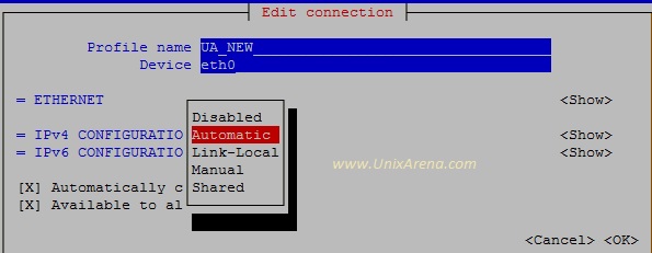
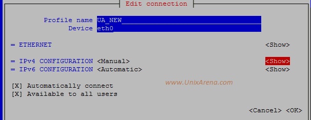
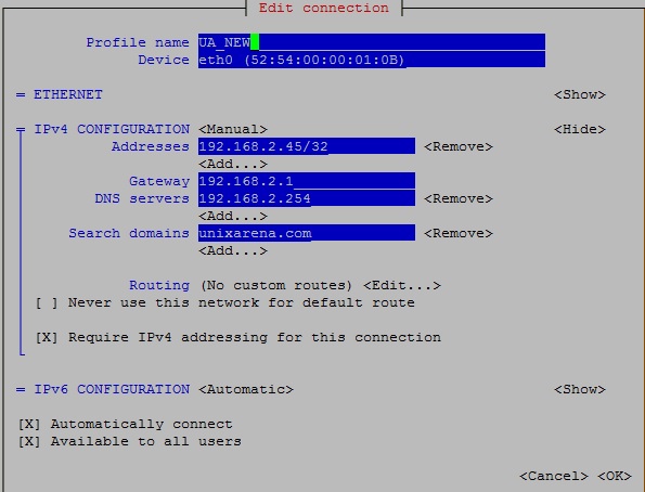
4. If you would like to configure the static IP for the new connection, you need to specify the IP address and gateway.

[root@server1-UA ~]#nmcli con add  con-name "UA_NEW-STATIC"  ifname eth0 autoconnect no type ethernet ip4 192.168.0.10/24 gw4 192.168.0.254
Connection 'UA_NEW-STATIC' (07279c85-6af2-4588-9313-cfb01ac1adae) successfully added.
[root@server1-UA ~]# nmcli con show
NAME           UUID                                  TYPE            DEVICE
UA_NEW-STATIC  07279c85-6af2-4588-9313-cfb01ac1adae  802-3-ethernet  --
UA_NEW         c511f74e-37f6-4746-ac15-be689210698b  802-3-ethernet  eth0
System eth0    5fb06bd0-0bb0-7ffb-45f1-d6edd65f3e03  802-3-ethernet  --
[root@server1-UA ~]#

5. Bring up the connection “UA_NEW-STATIC”

[root@server1-UA ~]#nmcli connection show
NAME           UUID                                  TYPE            DEVICE
UA_NEW-STATIC  07279c85-6af2-4588-9313-cfb01ac1adae  802-3-ethernet  eth0
UA_NEW         c511f74e-37f6-4746-ac15-be689210698b  802-3-ethernet  --
System eth0    5fb06bd0-0bb0-7ffb-45f1-d6edd65f3e03  802-3-ethernet  --
[root@server1-UA ~]#ip addr show
1: lo: <LOOPBACK,UP,LOWER_UP> mtu 65536 qdisc noqueue state UNKNOWN
    link/loopback 00:00:00:00:00:00 brd 00:00:00:00:00:00
    inet 127.0.0.1/8 scope host lo
       valid_lft forever preferred_lft forever
    inet6 ::1/128 scope host
       valid_lft forever preferred_lft forever
2: eth0: <BROADCAST,MULTICAST,UP,LOWER_UP> mtu 1500 qdisc pfifo_fast state UP ql                                                                                        en 1000
    link/ether 52:54:00:00:01:0b brd ff:ff:ff:ff:ff:ff
    inet 192.168.0.10/24 brd 192.168.0.255 scope global eth0
       valid_lft forever preferred_lft forever
    inet6 fe80::5054:ff:fe00:10b/64 scope link
       valid_lft forever preferred_lft forever
[root@server1-UA ~]#

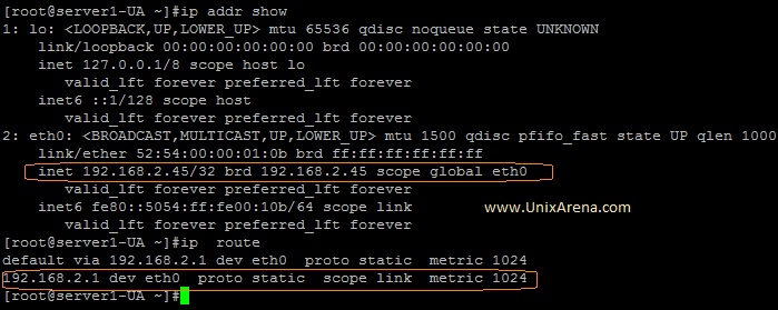
We have successfully configured the static IP for the interface eht0 using nmcli command.

If you would like to switch it back to other profile , just active the connection.

[root@server1-UA ~]#nmcli connection up "System eth0"
Connection successfully activated (D-Bus active path: /org/freedesktop/NetworkManager/ActiveConnection/4)
[root@server1-UA ~]#nmcli connection show
NAME           UUID                                  TYPE            DEVICE
UA_NEW-STATIC  07279c85-6af2-4588-9313-cfb01ac1adae  802-3-ethernet  --
UA_NEW         c511f74e-37f6-4746-ac15-be689210698b  802-3-ethernet  --
System eth0    5fb06bd0-0bb0-7ffb-45f1-d6edd65f3e03  802-3-ethernet  eth0
[root@server1-UA ~]#

6. How to configure the second IP on the existing network connection profile ?

We can add the additional IP on the existing connection  using “+” symbol. Here I am adding IP 192.168.0.20/24 and gateway 192.168.0.254 to the existing network connection “System eth0″.

[root@server1-UA ~]#nmcli con mod "System eth0" +ipv4.addresses "192.168.0.20/24 192.168.0.254"
[root@server1-UA ~]#ip addr show
1: lo: <LOOPBACK,UP,LOWER_UP> mtu 65536 qdisc noqueue state UNKNOWN
    link/loopback 00:00:00:00:00:00 brd 00:00:00:00:00:00
    inet 127.0.0.1/8 scope host lo
       valid_lft forever preferred_lft forever
    inet6 ::1/128 scope host
       valid_lft forever preferred_lft forever
2: eth0: <BROADCAST,MULTICAST,UP,LOWER_UP> mtu 1500 qdisc pfifo_fast state UP qlen 1000
    link/ether 52:54:00:00:01:0b brd ff:ff:ff:ff:ff:ff
    inet 172.25.2.251/16 brd 172.25.255.255 scope global eth0
       valid_lft forever preferred_lft forever
    inet6 fe80::5054:ff:fe00:10b/64 scope link
       valid_lft forever preferred_lft forever
[root@server1-UA ~]#

But it’s not reflecting the in “ip” command output. Let me bring the connection “up” again.(To refresh the connection)

[root@server1-UA ~]#nmcli con up "System eth0"
Connection successfully activated (D-Bus active path: /org/freedesktop/NetworkManager/ActiveConnection/6)
[root@server1-UA ~]#ip addr show
1: lo: <LOOPBACK,UP,LOWER_UP> mtu 65536 qdisc noqueue state UNKNOWN
    link/loopback 00:00:00:00:00:00 brd 00:00:00:00:00:00
    inet 127.0.0.1/8 scope host lo
       valid_lft forever preferred_lft forever
    inet6 ::1/128 scope host
       valid_lft forever preferred_lft forever
2: eth0: <BROADCAST,MULTICAST,UP,LOWER_UP> mtu 1500 qdisc pfifo_fast state UP qlen 1000
    link/ether 52:54:00:00:01:0b brd ff:ff:ff:ff:ff:ff
    inet 172.25.2.251/16 brd 172.25.255.255 scope global eth0
       valid_lft forever preferred_lft forever
    inet 192.168.0.20/24 brd 192.168.0.255 scope global eth0
       valid_lft forever preferred_lft forever
    inet6 fe80::5054:ff:fe00:10b/64 scope link tentative
       valid_lft forever preferred_lft forever
[root@server1-UA ~]#

We can see that both the IP’s are up on the network connection “System eth0″.

7. How to add the DNS server details using nmcli command ?

In RHEL 7 , /etc/resolv.conf will be managed by Network manager . So you need to use nmcli/nmtui command to up date the DNS server details ans domain name.

Here is my current /etc.resolv.conf file .

[root@server1-UA ~]#cat /etc/resolv.conf
# Generated by NetworkManager
search example.com
nameserver 172.25.2.251

Let me set the new DNS server IP using nmcli command.

[root@server1-UA ~]#nmcli con mod "System eth0" ipv4.dns 172.25.2.250

Bring up the connection and check the resolv.conf file. You can see the new changes.

[root@server1-UA ~]#nmcli con up "System eth0"
Connection successfully activated (D-Bus active path: /org/freedesktop/NetworkManager/ActiveConnection/12)
[root@server1-UA ~]#
[root@server1-UA ~]#cat /etc/resolv.conf
# Generated by NetworkManager
search example.com
nameserver 172.25.2.250
[root@server1-UA ~]#

Same way , you can update the domain name also.

[root@server1-UA ~]#nmcli con mod "System eth0" ipv4.dns-search example.com
[root@server1-UA ~]#nmcli con reload "System eth0"

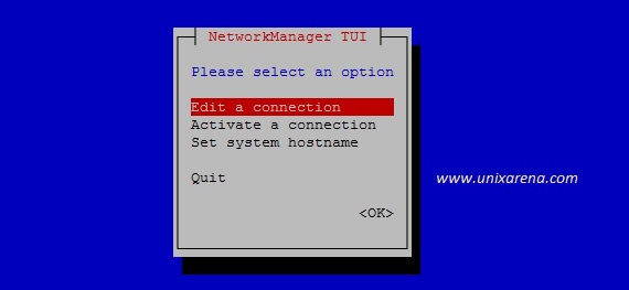
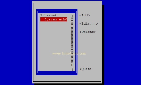
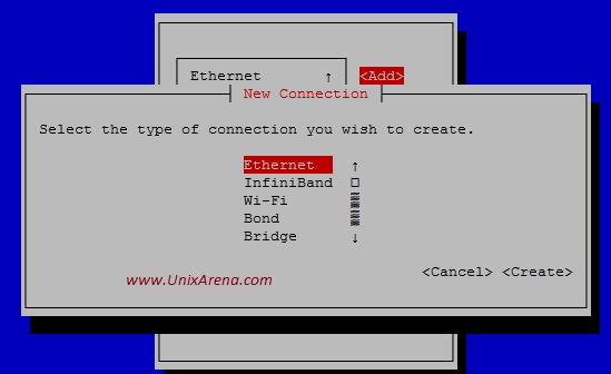
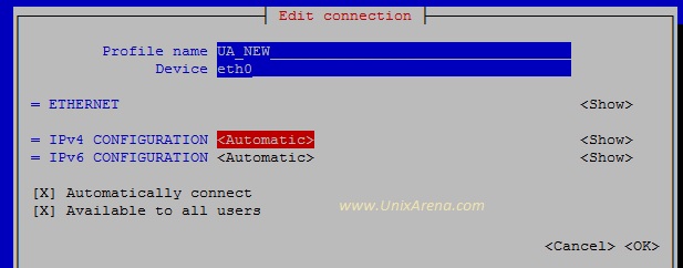
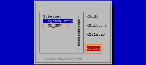
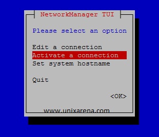
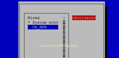
Hope this article is informative to you. If you are not comfortable with nmcli command, you can use nmtui which is text user interface. The next article will talk about “nmtui”.

To get the regular updates from UnixArena, Follow on

The post RHEL – 7 Managing the network with Network Manager appeared first on UnixArena.


RHEL – 7 Network Management – nmcli or nmtui

$
0
0

nmlci is a wonderful command to configure the network profiles on Redhat Enterprise Linux 7.  nmcli also supports the command completion function by pressing “tab” key but still you need to use the quotes properly.  nmtui is an alternative command for nmcli which is based on “Text User Interface”.  It will be useful for RHEL-7 Beginners but experienced system administrators will still prefer to use nmcli. Let’s play with nmtui .

Note: nmtui can be executed from putty and it doesn’t require graphical display.

Adding the new connection using nmtui
1. Login to RHEL7 and execute “nmtui” in putty terminal.

[root@server1-UA ~]#nmtui

2. Select edit connection and enter OK to continue.  (use tab key to navigate).

RHEL 7 nmtui

RHEL 7 nmtui

3. Here you can see the current network profile(System eth0). Select the “Add” and press enter to add new connection profile.

RHEL 7 - nmtui

RHEL 7 – nmtui

4.Once you select “Add”, you will get the below screen . Select “Ethernet” and create it .

RHEL 7 nmtui

RHEL 7 nmtui

5.Enter the new profile name and device name(existing device) for the new connection.  Select the “Automatic” and press enter.

RHLE-7 nmtui

RHLE-7 nmtui

You will get a option to select the connection type like below. Select “Manual” , if you want to configure the “static” IP.

RHEL-7 nmtui

RHEL-7 nmtui

6.Click on the “show” for IPv4  configuration.

RHEL 7 nmtui

RHEL 7 nmtui

7. Enter the IP,gateway and DNS servers details. Click “OK” to complete it .

RHEL 7 nmtui

RHEL 7 nmtui

8. Quit the nmtui .

RHEL-7 nmtui

RHEL-7 nmtui

At this point, we have successfully created the new network connection profile.But yet to activate it .

9. Let me activate the newly created profile using “nmtui”. Launch nmtui again.   Select “Activate a connection” and press “OK”.

RHEL-7 nmtui

RHEL-7 nmtui

10. Select the connection and activate it . At this point , your system will be switched to the new profile. So always activate the connection from console.

RHEL-7 nmtui

RHEL-7 nmtui

11.Let me check the connection details using nmcli command.

[root@server1-UA ~]#nmcli connection show
NAME         UUID                                  TYPE            DEVICE
UA_NEW       52569531-42ff-4b0d-91e8-b7d07d19c697  802-3-ethernet  eth0
System eth0  5fb06bd0-0bb0-7ffb-45f1-d6edd65f3e03  802-3-ethernet  ----
[root@server1-UA ~]#

12. Check the IP and route details using “ip” command.

RHEL-7 nmtui

RHEL-7 nmtui

We have successfully configured the new network profile and activated using nmtui

Hope this article is informative to you .

Share it ! Comment it !! Be Sociable !!!

The post RHEL – 7 Network Management – nmcli or nmtui appeared first on UnixArena.

Disk Partitioning – MBR vs GPT on RHEL -7

$
0
0

Disk partitioning allows a hard-drive to be divided in to multiple logical partitions on Redhat Enterprise Linux.  The multiple partitions can be used to create filesystems and it can be mounted in different mount points. Most of the operating systems are still using the MBR partitioning scheme and it has dictated how disks should be partitioned on systems running BIOS firmware. But it has lot of limitations since it stores the partition data in 32-bit values.

MBR Partitioning Limitations:

  • Can’t create more than 4 primary partitions from one disk.
  • With the help of extended partition, you can create up to 15 partitions.
  • Can’t partition the disk which more than 2TB

To overcome this limitations , We need to use GPT (GUID partitioning table) partitioning scheme. The systems which are using UEFI(Unified Extensible Firmware Interface) firmware, GPT is the standard for laying out partition tables on hard disks.

Here is the advantage of GPT table over MBR.

  • GPT supports up to 128 partitions
  • GPT allocates 64bits for logical block address
  • GPT supports disks up to 8 Zebibyte.

By default , MBR partitions must be managed by fdisk command. To manage the GPT disk , you need to use gdisk command.

If you would like to know that how to use the fdisk command, please go through this article.

In this article ,we will be experimenting with gdisk command.

1. Execute gdisk command for /dev/vda disk to list the existing partitions.

[root@server1-UA ~]#gdisk -l /dev/vda
GPT fdisk (gdisk) version 0.8.6

Partition table scan:
  MBR: MBR only
  BSD: not present
  APM: not present
  GPT: not present

***************************************************************
Found invalid GPT and valid MBR; converting MBR to GPT format.
***************************************************************

Disk /dev/vda: 20971520 sectors, 10.0 GiB
Logical sector size: 512 bytes
Disk identifier (GUID): 2525D738-DCC5-4E3E-BC30-677E43607CD4
Partition table holds up to 128 entries
First usable sector is 34, last usable sector is 20971486
Partitions will be aligned on 2048-sector boundaries
Total free space is 3168 sectors (1.5 MiB)

Number  Start (sector)    End (sector)  Size       Code  Name
   1            2048        20970332   10.0 GiB    8300  Linux filesystem
[root@server1-UA ~]#

In the above command output , you can see the warning message like “Found invalid GPT and valid MBR; converting MBR to GPT format” . It says that , if you modify the partition using gdisk , it will convert the MBR partition to GPT partition. This conversion will  corrupt the existing filesystems on the disk. Also , you should not use the gdisk command if the disk has MBR partition tables on it.

2. Execute gdisk command for /dev/vdb disk to list the existing partitions.

[root@server1-UA ~]#gdisk -l /dev/vdb
GPT fdisk (gdisk) version 0.8.6

Partition table scan:
  MBR: not present
  BSD: not present
  APM: not present
  GPT: not present

Creating new GPT entries.
Disk /dev/vdb: 20971520 sectors, 10.0 GiB
Logical sector size: 512 bytes
Disk identifier (GUID): 51A0F8D7-09BF-47D6-B84F-5BAE888EB534
Partition table holds up to 128 entries
First usable sector is 34, last usable sector is 20971486
Partitions will be aligned on 2048-sector boundaries
Total free space is 20971453 sectors (10.0 GiB)

Number  Start (sector)    End (sector)  Size       Code  Name
[root@server1-UA ~]#

In the above output , we can see that there is no MBR partition exists on that and also there is no warning about it.

3. Create a new partition with the size of 1GB on /dev/vdb.

[root@server1-UA ~]#gdisk /dev/vdb
GPT fdisk (gdisk) version 0.8.6

Partition table scan:
  MBR: not present
  BSD: not present
  APM: not present
  GPT: not present

Creating new GPT entries.

Command (? for help): m
b       back up GPT data to a file
c       change a partition's name
d       delete a partition
i       show detailed information on a partition
l       list known partition types
n       add a new partition
o       create a new empty GUID partition table (GPT)
p       print the partition table
q       quit without saving changes
r       recovery and transformation options (experts only)
s       sort partitions
t       change a partition's type code
v       verify disk
w       write table to disk and exit
x       extra functionality (experts only)
?       print this menu

Command (? for help): n
Partition number (1-128, default 1):
First sector (34-20971486, default = 2048) or {+-}size{KMGTP}:
Last sector (2048-20971486, default = 20971486) or {+-}size{KMGTP}: +1G
Current type is 'Linux filesystem'
Hex code or GUID (L to show codes, Enter = 8300):
Changed type of partition to 'Linux filesystem'

Command (? for help): p
Disk /dev/vdb: 20971520 sectors, 10.0 GiB
Logical sector size: 512 bytes
Disk identifier (GUID): 6BE88D5A-0E83-44A6-B1BD-5A2C064E24EC
Partition table holds up to 128 entries
First usable sector is 34, last usable sector is 20971486
Partitions will be aligned on 2048-sector boundaries
Total free space is 18874301 sectors (9.0 GiB)

Number  Start (sector)    End (sector)  Size       Code  Name
   1            2048         2099199   1024.0 MiB  8300  Linux filesystem
Command (? for help): w

Final checks complete. About to write GPT data. THIS WILL OVERWRITE EXISTING
PARTITIONS!!

Do you want to proceed? (Y/N): y
OK; writing new GUID partition table (GPT) to /dev/vdb.
The operation has completed successfully.
[root@server1-UA ~]#

Let me verify the newly created partition table.

[root@server1-UA ~]#gdisk -l /dev/vdb
GPT fdisk (gdisk) version 0.8.6

Partition table scan:
  MBR: protective
  BSD: not present
  APM: not present
  GPT: present

Found valid GPT with protective MBR; using GPT.
Disk /dev/vdb: 20971520 sectors, 10.0 GiB
Logical sector size: 512 bytes
Disk identifier (GUID): 6BE88D5A-0E83-44A6-B1BD-5A2C064E24EC
Partition table holds up to 128 entries
First usable sector is 34, last usable sector is 20971486
Partitions will be aligned on 2048-sector boundaries
Total free space is 18874301 sectors (9.0 GiB)

Number  Start (sector)    End (sector)  Size       Code  Name
   1            2048         2099199   1024.0 MiB  8300  Linux filesystem
[root@server1-UA ~]#

4.Inform to the kernel to re-read the partition table of /dev/vdb.

[root@server1-UA ~]#partprobe /dev/vdb
[root@server1-UA ~]#

5.Create a new filesystem on top /dev/vdb1 partition which we have created now.

[root@server1-UA ~]#mkfs.ext4 /dev/vdb1
mke2fs 1.42.9 (28-Dec-2013)
Filesystem label=
OS type: Linux
Block size=4096 (log=2)
Fragment size=4096 (log=2)
Stride=0 blocks, Stripe width=0 blocks
65536 inodes, 262144 blocks
13107 blocks (5.00%) reserved for the super user
First data block=0
Maximum filesystem blocks=268435456
8 block groups
32768 blocks per group, 32768 fragments per group
8192 inodes per group
Superblock backups stored on blocks:
        32768, 98304, 163840, 229376

Allocating group tables: done
Writing inode tables: done
Creating journal (8192 blocks): done
Writing superblocks and filesystem accounting information: done

[root@server1-UA ~]#

5.Mount the partition .

[root@server1-UA ~]#mkdir /gdisk_exp
[root@server1-UA ~]#mount -t ext4 /dev/vdb1 /gdisk_exp
[root@server1-UA ~]#df -h /gdisk_exp
Filesystem      Size  Used Avail Use% Mounted on
/dev/vdb1       976M  2.6M  907M   1% /gdisk_exp
[root@server1-UA ~]#

6.Let me add new partition on the same disk.

[root@server1-UA ~]#gdisk /dev/vdb
GPT fdisk (gdisk) version 0.8.6

Partition table scan:
  MBR: protective
  BSD: not present
  APM: not present
  GPT: present

Found valid GPT with protective MBR; using GPT.

Command (? for help): p
Disk /dev/vdb: 20971520 sectors, 10.0 GiB
Logical sector size: 512 bytes
Disk identifier (GUID): 6BE88D5A-0E83-44A6-B1BD-5A2C064E24EC
Partition table holds up to 164 entries
First usable sector is 43, last usable sector is 20971477
Partitions will be aligned on 2048-sector boundaries
Total free space is 18874283 sectors (9.0 GiB)

Number  Start (sector)    End (sector)  Size       Code  Name
   1            2048         2099199   1024.0 MiB  8300  Linux filesystem

Command (? for help): n
Partition number (2-164, default 2):
First sector (43-20971477, default = 2099200) or {+-}size{KMGTP}:
Last sector (2099200-20971477, default = 20971477) or {+-}size{KMGTP}: +1G
Current type is 'Linux filesystem'
Hex code or GUID (L to show codes, Enter = 8300):
Changed type of partition to 'Linux filesystem'

Command (? for help): p
Disk /dev/vdb: 20971520 sectors, 10.0 GiB
Logical sector size: 512 bytes
Disk identifier (GUID): 6BE88D5A-0E83-44A6-B1BD-5A2C064E24EC
Partition table holds up to 164 entries
First usable sector is 43, last usable sector is 20971477
Partitions will be aligned on 2048-sector boundaries
Total free space is 16777131 sectors (8.0 GiB)

Number  Start (sector)    End (sector)  Size       Code  Name
   1            2048         2099199   1024.0 MiB  8300  Linux filesystem
   2         2099200         4196351   1024.0 MiB  8300  Linux filesystem

Command (? for help): w

Final checks complete. About to write GPT data. THIS WILL OVERWRITE EXISTING
PARTITIONS!!

Do you want to proceed? (Y/N): y
OK; writing new GUID partition table (GPT) to /dev/vdb.
The operation has completed successfully.
[root@server1-UA ~]#

Re-read the partition and create the new filesystem .

[root@server1-UA ~]#partprobe /dev/vdb
[root@server1-UA ~]#[root@server1-UA ~]#mkfs.ext4 /dev/vdb2
mke2fs 1.42.9 (28-Dec-2013)
Filesystem label=
OS type: Linux
Block size=4096 (log=2)
Fragment size=4096 (log=2)
Stride=0 blocks, Stripe width=0 blocks
65536 inodes, 262144 blocks
13107 blocks (5.00%) reserved for the super user
First data block=0
Maximum filesystem blocks=268435456
8 block groups
32768 blocks per group, 32768 fragments per group
8192 inodes per group
Superblock backups stored on blocks:
        32768, 98304, 163840, 229376

Allocating group tables: done
Writing inode tables: done
Creating journal (8192 blocks): done
Writing superblocks and filesystem accounting information: done

[root@server1-UA ~]#mount -t ext4 /dev/vdb2 /gdisk_exp2
[root@server1-UA ~]#df -h -F ext4
Filesystem      Size  Used Avail Use% Mounted on
/dev/vdb1       976M  2.6M  907M   1% /gdisk_exp
/dev/vdb2       976M  2.6M  907M   1% /gdisk_exp2
[root@server1-UA ~]#

6. Update the /etc/fstab file to mount the filesystems across the system reboot.

In RHEl 7 , fstab will be looking like below.

[root@server1-UA ~]#cat /etc/fstab
#
# /etc/fstab
# Created by anaconda on Wed May  7 01:22:57 2014
#
# Accessible filesystems, by reference, are maintained under '/dev/disk'
# See man pages fstab(5), findfs(8), mount(8) and/or blkid(8) for more info
#
UUID=9bf6b9f7-92ad-441b-848e-0257cbb883d1 /                       xfs     defaults        1 1
[root@server1-UA ~]#

Note: It is recommend to use “UUID” instead of directly specifying the device name in the fstab. The device name might get change when you do SAN migration or modifying the underlying physical machine. Normally UUID stores in the super-block and it remain intact in the superblock of the device irrespective of those changes.

Let’s see that how we can find the UUID for the newly created filesystem.

Use blkid command to find the UUID for all the filesystems .

[root@server1-UA ~]#blkid
/dev/vda1: UUID="9bf6b9f7-92ad-441b-848e-0257cbb883d1" TYPE="xfs"
/dev/vdb1: UUID="fee52e0a-25b5-470e-a946-ecb385a493fd" TYPE="ext4" PARTLABEL="Linux filesystem" PARTUUID="199829ed-108e-4ce3-a9c1-080a10c6296b"
/dev/vdb2: UUID="0f52dc0c-21c8-471e-a63a-fbca9ebbb66c" TYPE="ext4" PARTLABEL="Linux filesystem" PARTUUID="adf6934c-a6c3-4e26-9247-22401fc9b462"
[root@server1-UA ~]#

Let me update the /etc/fstab using the UUID information for /dev/vdb1 and /dev/vdb2 .

[root@server1-UA ~]#cat /etc/fstab

#
# /etc/fstab
# Created by anaconda on Wed May  7 01:22:57 2014
#
# Accessible filesystems, by reference, are maintained under '/dev/disk'
# See man pages fstab(5), findfs(8), mount(8) and/or blkid(8) for more info
#
UUID=9bf6b9f7-92ad-441b-848e-0257cbb883d1 /                       xfs     defaults        1 1
UUID=fee52e0a-25b5-470e-a946-ecb385a493fd       /gdisk_exp      ext4    defaults        1 1
UUID=0f52dc0c-21c8-471e-a63a-fbca9ebbb66c       /gdisk_exp2     ext4    defaults        1 1
[root@server1-UA ~]#

Let me re-mount the filesystem using mountpoint.

[root@server1-UA ~]#umount /gdisk_exp
[root@server1-UA ~]#umount /gdisk_exp2
[root@server1-UA ~]#mount /gdisk_exp
[root@server1-UA ~]#mount /gdisk_exp2
[root@server1-UA ~]#df -h -F ext4
Filesystem      Size  Used Avail Use% Mounted on
/dev/vdb1       976M  2.6M  907M   1% /gdisk_exp
/dev/vdb2       976M  2.6M  907M   1% /gdisk_exp2
[root@server1-UA ~]#

The above output confirms that /etc/fstab entries are correct .

Hope this article is informative to you.

Share ! Comment it !! Be Sociable !!!

The post Disk Partitioning – MBR vs GPT on RHEL -7 appeared first on UnixArena.

Are you in VM or Physical host ? RHEL -7

$
0
0

The whole world is moving towards virtualization. Unless you maintain the inventory on CMDB , it is very difficult to find the server location and configuration. The hyper-visors like VMware vSphere, Microsoft Hyper-V,  Xen and KVM supports Linux as virtual machine. If you have the proper CMDB for the virtual machine, you can easily find the hyper-visor for the VM and its location. Otherwise, you need to struggle little bit. Here we will examine such a scenario for Redhat Enterprise Linux 7 VM.

1. How to find the whether the system is physical machine or VM ?

Execute command called “virt-what” to know whether you are in physical machine or virtual machine .

[root@foundation1 ~]# virt-what

[root@foundation1 ~]#
[root@server1-UA ~]#echo $?
0
[root@server1-UA ~]#

If nothing is printed and the script exits with code 0 (no error), then it can mean either that the program is running on bare-metal or the program is running inside a type of virtual machine which we don’t know about or cannot detect.

2.If the system is virtual machine ,you will get the hyper-visor name like below.

[root@foundation1 ~]# virt-what
vmware
[root@foundation1 ~]#

The above output shows that VM is running on top of VMware hyper-visors. It can be vmware ESXi or VMware workstation/Fusion

3.If the host is running on top of Linux machine using KVM, you will get the output like below.

[root@server1-UA ~]#virt-what
kvm
[root@server1-UA ~]#

4.Xen virtual machines will display like below.

[root@server1-UA ~]# virt-what
xen
xen-domU
[root@server1-UA ~]#

About virt-what:
virt-what is a shell script which can be used to detect if the program is running in a virtual machine or not. virt-what supports a very large number of different hypervisor types, including common open source hypervisors (KVM, Xen, QEMU, VirtualBox), mainframe systems like IBM Systemz, LPAR, z/VM, hardware partitioning schemes like Hitachi Virtage, proprietary hypervisors like VMWare, Microsoft Hyper-V.

virt-what is already packaged in Fedora (13+), Red Hat Enterprise Linux (5.7+ and 6.1+), Debian, Ubuntu, ArchLinux and Gentoo. If you don’t have the utility , download the source and compile it . virt-what source is available here.

virt-what has been developed by Redhat community.

Hope this article is informative to you.  Share it ! Comment it !! Be Sociable !!!

The post Are you in VM or Physical host ? RHEL -7 appeared first on UnixArena.

Playing with firewalld on RHEL 7

$
0
0

The Linux kernel includes a powerful network filtering subsystem called netfilter.  The netfilter subsystem allows kernel modules to inspect every packet which are travelling to the system. Any incoming, outgoing and forwarded network packets cab e be inspected, modified ,dropped or rejected in a programmatic way ,before reaching to the user space. But these programs needs to be defined and injected to netfilter. This can be done in two ways prior to the RHEL 7.

  1. Write the custom kernel modules to interact with netfilter.
  2. Use the iptables command to define the rules.

In the practical  world,  we will be using iptables command to define the firewall rules. But iptables is very low level program and very difficult to write the rules. Also iptables doesn’t support ipv6. That’s why Redhat has come up with the new utility called “firewalld” which used to interact with netfilter to define the rules.

In this article ,we will see the basic operations of firewalld using firewall-config. (GUI based)

By default firewalld is installed with base RHEL7 installation , but it is not available if you go with the minimal installation.

1. To install the firewalld, use the below command.

[root@server1-UA ~]#yum install firewalld
Loaded plugins: langpacks
rhel_dvd                                                                                                                                         | 4.1 kB  00:00:00
(1/2): rhel_dvd/group_gz                                                                                                                         | 134 kB  00:00:00
(2/2): rhel_dvd/primary_db                                                                                                                       | 3.4 MB  00:00:00
Package firewalld-0.3.9-7.el7.noarch already installed and latest version
Nothing to do
[root@server1-UA ~]#

2.There are three ways to interact with firewalld. (To configure firewalld)

  • Directly editing configuration files in /etc/firewalld.
  • Using the graphical firewall-config tool.
  • Using firewall-cmd from command line

If you couldn’t find “firewall-config” command, you can use the below command to install the package.

[root@server1-UA ~]#yum install firewall-config
Loaded plugins: langpacks
Package firewall-config-0.3.9-7.el7.noarch already installed and latest version
Nothing to do
[root@server1-UA ~]#

Let’s see how the firewall-config’s graphical window works.

Server – Redhat Enterprise Linux  7 .

1. Login to the server and execute command “firewall-config” from the graphical terminal. You will get the window like below.

# firewall-config

Firewall-config RHEL7

By default, firewalld will be installed with pre-defined zones. Here public the default zone and & currently loaded.

You can check the currently loaded zone  using below options as well .

Currently loaded zone

2. Install httpd package for testing purpose.

[root@server1-UA firewalld]#yum install httpd
Loaded plugins: langpacks
Resolving Dependencies
--> Running transaction check
---> Package httpd.x86_64 0:2.4.6-17.el7 will be installed
--> Processing Dependency: httpd-tools = 2.4.6-17.el7 for package: httpd-2.4.6-17.el7.x86_64
--> Processing Dependency: /etc/mime.types for package: httpd-2.4.6-17.el7.x86_64
--> Processing Dependency: libapr-1.so.0()(64bit) for package: httpd-2.4.6-17.el7.x86_64
--> Processing Dependency: libaprutil-1.so.0()(64bit) for package: httpd-2.4.6-17.el7.x86_64
--> Running transaction check
---> Package apr.x86_64 0:1.4.8-3.el7 will be installed
---> Package apr-util.x86_64 0:1.5.2-6.el7 will be installed
---> Package httpd-tools.x86_64 0:2.4.6-17.el7 will be installed
---> Package mailcap.noarch 0:2.1.41-2.el7 will be installed
--> Finished Dependency Resolution

Dependencies Resolved

======================================================
 Package      Arch    Version       Repository Size
======================================================
Installing:
 httpd        x86_64  2.4.6-17.el7  rhel_dvd  1.2 M
Installing for dependencies:
 apr          x86_64  1.4.8-3.el7   rhel_dvd  103 k
 apr-util     x86_64  1.5.2-6.el7   rhel_dvd   92 k
 httpd-tools  x86_64  2.4.6-17.el7  rhel_dvd   77 k
 mailcap      noarch  2.1.41-2.el7  rhel_dvd   31 k

Transaction Summary
======================================================
Install  1 Package (+4 Dependent packages)

Total download size: 1.5 M
Installed size: 4.3 M
Is this ok [y/d/N]: y
Downloading packages:
(1/5): apr-1.4.8-3.el7.x86_64.rpm                         | 103 kB  00:00:00
(2/5): apr-util-1.5.2-6.el7.x86_64.rpm                    |  92 kB  00:00:00
(3/5): httpd-tools-2.4.6-17.el7.x86_64.rpm                |  77 kB  00:00:00
(4/5): httpd-2.4.6-17.el7.x86_64.rpm                      | 1.2 MB  00:00:00
(5/5): mailcap-2.1.41-2.el7.noarch.rpm                    |  31 kB  00:00:00
-----------------------------------------------------------------------------
Total               2.4 MB/s | 1.5 MB  00:00:00
Running transaction check
Running transaction test
Transaction test succeeded
Running transaction
  Installing : apr-1.4.8-3.el7.x86_64           1/5
  Installing : apr-util-1.5.2-6.el7.x86_64      2/5
  Installing : httpd-tools-2.4.6-17.el7.x86_64  3/5
  Installing : mailcap-2.1.41-2.el7.noarch      4/5
  Installing : httpd-2.4.6-17.el7.x86_64        5/5
  Verifying  : mailcap-2.1.41-2.el7.noarch      1/5
  Verifying  : httpd-tools-2.4.6-17.el7.x86_64  2/5
  Verifying  : apr-1.4.8-3.el7.x86_64           3/5
  Verifying  : apr-util-1.5.2-6.el7.x86_64      4/5
  Verifying  : httpd-2.4.6-17.el7.x86_64        5/5

Installed:
  httpd.x86_64 0:2.4.6-17.el7

Dependency Installed:
apr.x86_64 0:1.4.8-3.el7             apr-util.x86_64 0:1.5.2-6.el7             
httpd-tools.x86_64 0:2.4.6-17.el7       mailcap.noarch 0:2.1.41-2.el7

Complete!
[root@server1-UA firewalld]#

3.Start the httpd service using systemctl command.

[root@server1-UA firewalld]#systemctl enable httpd
ln -s '/usr/lib/systemd/system/httpd.service' '/etc/systemd/system/multi-user.target.wants/httpd.service'
[root@server1-UA firewalld]#systemctl start httpd
[root@server1-UA firewalld]#systemctl status httpd
httpd.service - The Apache HTTP Server
   Loaded: loaded (/usr/lib/systemd/system/httpd.service; enabled)
   Active: active (running) since Thu 2015-04-23 17:32:42 EDT; 1s ago
 Main PID: 7783 (httpd)
   Status: "Processing requests..."
   CGroup: /system.slice/httpd.service
           ├─7783 /usr/sbin/httpd -DFOREGROUND
           ├─7784 /usr/sbin/httpd -DFOREGROUND
           ├─7785 /usr/sbin/httpd -DFOREGROUND
           ├─7786 /usr/sbin/httpd -DFOREGROUND
           ├─7787 /usr/sbin/httpd -DFOREGROUND
           └─7788 /usr/sbin/httpd -DFOREGROUND

Apr 23 17:32:42 server1.example.com systemd[1]: Started The Apache HTTP Server.
[root@server1-UA firewalld]#

4.Make sure that you have already  disabled the iptables service and verify that firewalld is online.

[root@server1-UA firewalld]#systemctl mask iptables.service
ln -s '/dev/null' '/etc/systemd/system/iptables.service'
[root@server1-UA firewalld]#systemctl mask ip6tables.service
ln -s '/dev/null' '/etc/systemd/system/ip6tables.service'
[root@server1-UA firewalld]#systemctl status firewalld.service
firewalld.service - firewalld - dynamic firewall daemon
   Loaded: loaded (/usr/lib/systemd/system/firewalld.service; enabled)
   Active: active (running) since Wed 2015-04-22 22:59:42 EDT; 18h ago
 Main PID: 463 (firewalld)
   CGroup: /system.slice/firewalld.service
           └─463 /usr/bin/python -Es /usr/sbin/firewalld --nofork --nopid

Apr 22 22:59:42 server1.example.com systemd[1]: Started firewalld - dynamic firewall daemon.
[root@server1-UA firewalld]#

5.Create the index.html file under /var/www/html directory.

[root@server1-UA /]#cd /var/www/html/
[root@server1-UA html]#ls -lrt
total 0
[root@server1-UA html]#touch index.html
[root@server1-UA html]# echo "welcome to UnixArena" > index.html 
total 12
-rw-r--r--. 1 root root 0 Apr 23 17:51 index.html
[root@server1-UA html]#

6. Open the browser & enter the server IP. You will get the webpage like below.

Try to access webpage

7. Try to access the server from other host’s browser. Webpage will not be loaded by default. Because system firewall has blocked  the  external IP.

8. Let me try to open a port to the external network in the firewall-config. Select “runtime” in the configuration and select “http” to open the port in runtime.

Check the "http"
Check the “http”

9.From the options , reload the firewalld.

Reload the firewalld

At this point , you should be able to access the webpage from external network.

If you would like to make the changes permanently(To open the port for service http), select the “permanent” from configuration tab and select http in the service tab.

Opening port permanently

Hope this article helps.

Share it ! Comment it !! Be Sociable !!!

The post Playing with firewalld on RHEL 7 appeared first on UnixArena.

How to configure the firewall using firewall-cmd ?

$
0
0

In the last article, we have opened the port (80) for http service using firewall-config graphical utility in Redhat Enterprise Linux  7.  As a Unix/Linux admin , would you prefer to use “GUI” over “command line” ? I don’t think so. Most of the Unix/Linux system administrators will go with the command line. firewall-cmd is a command line utility which interact with netfiler to configure the firewall rules on RHEL-7. In this article ,we will be doing the same work what we have done using firewall-config in the last article by using firewall-cmd command for different ports and services.

1. Get the default firewall zone on the server.

[root@server1-UA ~]#firewall-cmd --get-default-zone
public
[root@server1-UA ~]#

2. Get the currently active zone .

[root@server1-UA ~]#firewall-cmd --get-active-zones
public
  interfaces: eth0
[root@server1-UA ~]#

3.List all configured interfaces , sources, services, and ports for specific zone. If you didn’t specify the zone , it will provide the information for the currently active zone.

[root@server1-UA ~]#firewall-cmd --list-all --zone=public
public (default, active)
  interfaces: eth0
  sources:
  services: dhcpv6-client http ssh
  ports:
  masquerade: no
  forward-ports:
  icmp-blocks:
  rich rules:

[root@server1-UA ~]#

In the above command output, you can see that dhcpv6-client, http and ssh ports are curretnly opened.

You need to follow the below procedure, if there is a requirement to open a new port called 8090/tcp on the system.

1. Assume that currently active and default firewall zone is public.

2. Let me open the port 8090 using firewall-cmd.

[root@server1-UA ~]#firewall-cmd --permanent --add-port=8090/tcp --zone=public
success
[root@server1-UA ~]#

3. Re-load the firewalld.
[root@server1-UA ~]#firewall-cmd –reload
success
[root@server1-UA ~]#

4. Verify the changes using firewall-cmd.

[root@server1-UA ~]#firewall-cmd --list-all
public (default, active)
  interfaces: eth0
  sources:
  services: dhcpv6-client http ssh
  ports: 8090/tcp
  masquerade: no
  forward-ports:
  icmp-blocks:
  rich rules:

[root@server1-UA ~]#

In the above command output, you can see that 8090/tcp has been added.

Please follow the below procedure , if you would like to add service called ldap. ldap ports needs to defined in /etc/services file.

[root@server1-UA ~]#firewall-cmd --permanent --add-service=ldap --zone=public
success
[root@server1-UA ~]#firewall-cmd --reload
success
[root@server1-UA ~]#firewall-cmd --list-all --permanent --zone=public
public (default)
  interfaces:
  sources:
  services: dhcpv6-client http ldap ssh
  ports: 8090/tcp
  masquerade: no
  forward-ports:
  icmp-blocks:
  rich rules:
[root@server1-UA ~]#

How to block the currently opened ports/services ?

*    In the below example, I have blocked the port 8090/tcp .

[root@server1-UA ~]#firewall-cmd --permanent --remove-port=8090/tcp --zone=public
success
[root@server1-UA ~]#firewall-cmd --list-all --permanent --zone=public
public (default)
  interfaces:
  sources:
  services: dhcpv6-client http ldap ssh
  ports:
  masquerade: no
  forward-ports:
  icmp-blocks:
  rich rules:
[root@server1-UA ~]#firewall-cmd --reload
success
[root@server1-UA ~]#

*    In the below example, i have blocked the http service.

[root@server1-UA ~]#firewall-cmd --permanent --remove-service=http --zone=public
success
[root@server1-UA ~]#firewall-cmd --reload
success
[root@server1-UA ~]#firewall-cmd --list-all --permanent --zone=public
public (default)
  interfaces:
  sources:
  services: dhcpv6-client ldap ssh
  ports:
  masquerade: no
  forward-ports:
  icmp-blocks:
  rich rules:
[root@server1-UA ~]#

firewall-cmd is very simple and easy to use unlike the iptables. Hope everybody loves it .

Share it ! Comment it !! Be Sociable !!!

The post How to configure the firewall using firewall-cmd ? appeared first on UnixArena.

VMware vSphere 6.0 vs vSphere 5.x – Difference

$
0
0

In March 2015, VMware has released the much-awaited VMware vSphere 6.0 .  Is it completely different from the previous VMware releases vSphere 5.5 and vSphere 5.1 ? No.  The most of the features are remains same but there are lot of enhancement made on the existing features. For an example, VMware has brought lot improvements on the VM Fault tolerance in vSphere 6.0. Also there are few new features introduced  in the VMware vSphere 6.0. Let’s see the new features of VMware vSphere 6.0. In the bottom of the article ,I have listed the differences between the vSphere 6.0 , vSphere 5.5 and vSphere 5.1 versions.

What’s New in VMware vSphere 6.0 ?

  1. VMware vSphere Virtual Volumes. (vvols)
  2. vSphere Content Library .
  3. Cross-vCenter Clone and Migration

Enhancement Area’s:

  1. Increased Scalability
  2. Expanded Support
  3. Amazing Graphics with NVIDIA
  4. Instant 10x Faster Clone
  5. Network IO Control
  6. Multicast Snooping
  7. Multiple TCP/IP Stack for vMotion
  8. vMotion Enhancements (over distances of up to 100ms RTT. )
  9. Replication-Assisted vMotion
  10. Fault Tolerance (up to 4-vCPUs)
  11. Enhanced User Interface (web client)

Let’s see the comparison between VMware vSphere 6.0 and VMware vSphere 5.5 & 5.1 versions.

ESXi – Hypervisor Level – Comparison:

Hyper-visor Level  comparison - VMware
Hyper-visor Level comparison – VMware

Virtual Machine Level Difference:

Virtual Machine Level Comparision
Virtual Machine Level Comparison

VMware vCenter Level Differences:

VMware vCenter Level Comparision
VMware vCenter Level Comparison

Hope this article is informative to you. Share it ! Be Sociable !!

Sources:

  • http://www.vmware.com/files/pdf/vsphere/VMW-WP-vSPHR-Whats-New-6-0.pdf
  • https://www.vmware.com/pdf/vsphere5/r50/vsphere-50-configuration-maximums.pdf
  • https://pubs.vmware.com/vsphere-51/topic/com.vmware.ICbase/PDF/vsphere-esxi-vcenter-server-51-availability-guide.pdf

The post VMware vSphere 6.0 vs vSphere 5.x – Difference appeared first on UnixArena.

How to install VMware vSphere 6.0 ESXi

$
0
0

In this article , we will see the installation of vSphere 6.0 VMware ESXi . There are multiple ways to install the ESXi. If you are planning to install less than 10 ESXi hosts, you can prefer the  typical interactive installation method. In this method, we need to boot the physical X86 server using the ESXi installer DVD and respond to the installer prompts to install ESXi to the local host disk. The ESXi installer re-formats and partitions the target disk and installs the ESXi boot image. If the target disk doesn’t have existing ESXi installation , the installer overwrites the existing data on the disk, partitions and other operating systems.

1. Insert the vSphere 6.0 VMware ESXi installer DVD in to the system.

2. Boot the system from DVD drive. (Selecting from BIOS Menu). You will see the standard ESXi 6.0 Boot Menu like below. Press “Enter” to continue

VMware ESXi 6.0 installation - Boot Menu
VMware ESXi 6.0 installation – Boot Menu

VMware ESXi will load the necessary libraries to install the hyper-visor.

VMware ESXi 6.0 installation

3.Go through the VMware hardware compatibility guide  to see whether your hardware is listed or not. If your hardware is not listed, then you can’t get the support from VMware for the host. Press “Enter” to continue.

VMware ESXi 6.0 installation

4. Accept the end user licence agreement by pressing F11.

VMware ESXi 6.0 installation

Scanning  the available devices.

VMware ESXi 6.0 installation

5. Select the disk for the ESXi installation and “Enter” to continue.

VMware ESXi 6.0 installation

Note: For demonstration purpose , I am installing the ESXi on the VMware workstation.

6.Select the keyboard layout.

VMware ESXi 6.0 installation

7. Set the root password for the hypervisor.

VMware ESXi 6.0 installation

8.Press F11 to begin the installation.

VMware ESXi 6.0 installation

9.Press “Enter” to reboot the host to complete the installation.

VMware ESXi 6.0 installation

System is rebooting .

VMware ESXi 6.0 installation

After the installation , system will come up with DHCP IP and hostname as “localhost”.

VMware ESXi 6.0 installation

Hope this article is informative to you. In the next article ,we will see that how to configure the  VMware ESXi 6.0 ‘s networking and changing the hostname to desired one.

Thank you for visiting UnixArena.

The post How to install VMware vSphere 6.0 ESXi appeared first on UnixArena.


How to Configure the networking on VMware ESXi 6.0 ?

$
0
0

Once you have installed the VMware ESXi 6.0 using the interactive installer , You need to configure the network and set the hostname. By default, it takes the IP from DHCP and it sets the hostname as “localhost”. In this article ,we will see the post installation of VMware ESXi 6.0.  In the Enterprise setup, ESXi hosts will be managed via VMware vCenter server. To connect to the vCenter server , you must have assigned the valid IP address on the ESXi host. In this article, we will see that how to set the static IP address on the ESXi 6.0. In the end of the article, we will see the  demonstration of  changing the ESXi hostname.

Configuring the Static IP on VMware ESXi 6.0

1. If you have followed the previous article, you can see that, system has been installed successfully and it has been booted with DHCP IP.

VMware vSphere 6.0 - Post Installation
VMware vSphere 6.0 – Post Installation


2. Press F2 to get the login screen. Login as root user.

VMware ESXi 6.0 installation


3.Use the arrow keys and navigate it to “Configure Management network” & Press Enter.

ESXi Network Management


4.Navigate to IPV4  using the arrow keys and press enter.

ESXi IP
ESXi IP


5.Use the arrow keys and select “set static IPv4 address & network configuration”  and enter the IP/Netmask/gateway details. < Enter > OK

Set the static IP
Set the static IP

You will be re-directed to the below screen after setting the new static IP.

Verify the IP details


6.Press “Esc” key . It will prompt you to restart the management network services.  Select “yes”  to restart it .

VMware ESXi 6.0 installation


Changing the hostname for VMware ESXi host:

1. Navigate to “configure Management Network”

configure Management Network


2.Navigate to “DNS configuration” and press enter

changing the hostname


3.Enter the hostname and update the DNS server details.

Enter the hostname & DNS server details


4.Press “Escape” to save the host configuration and restart the network . press “Y” to continue.

confirm for management network restart


5. Verify the hostname & IP information which we have changed .

verify the IP & hostname info

We have successfully  configured the VMware ESXi  networking  and  changed the hostname. At this point, our ESXi host is ready to connect with vCenter server.

Hope this article is informative to you .

The post How to Configure the networking on VMware ESXi 6.0 ? appeared first on UnixArena.

How to deploy VCSA 6.0 on VMware workstation ?

$
0
0

VMware VCSA (vCenter Server Appliance) 6.0 has eliminated the previous releases limitations and issues. Now VCSA 6.0 is able to provide the all the features what the Windows vCenter servers is providing currently. In other words , there is no difference between Windows vCenter and VCSA. So it s up to the customer to choose what they need on their environment. VMware has changed the way of deploying the VCSA completely and its not straight forward to deploy in VMware workstation/Fusion. But its quite easy when you deploy as VM in VMware ESXi host. In this article ,we will see that how to deploy the VMware  VCSA (vCenter Server Appliance) 6.0 on VMware workstation.

Task:1

1. Download the VCSA 6.0 from VMware website.

Download VCSA 6.0 from VMware


2. Use the power ISO to extract the ISO file or you can mount the ISO file on the virtual CD drive.

After Extracting the ISO


3. Navigate to vcsa directory.

VMware VCSA
VMware VCSA


4. By Default, vmware-vcsa file be without extension of “.ova” .  Just rename the file “vmware-vcsa” as “vmware-vcsa.ova”.

Make it as OVA
Make it as OVA


5. Open the VMware workstation 10 . Click on File -> Open .

VMware workstation Open


6.Select the file “vmware-vcsa.ova”

Storage path for VCSA
Importing the OVA
Importing the OVA


7.Accept the License.

Accept the License


8.The new VM will be created like below.  Do not power on the VM.

VM is created
VM is created


9.Edit the VM’s vmx file.

Edit the vmx file
Edit the vmx file

Add the below lines in the end of the vmx file and save it .

guestinfo.cis.appliance.net.addr.family = "ipv4"
guestinfo.cis.appliance.net.mode = "static"
guestinfo.cis.appliance.net.addr = "172.25.2.150"
guestinfo.cis.appliance.net.prefix = "24"
guestinfo.cis.appliance.net.gateway = "172.25.2.190"
guestinfo.cis.vmdir.password = "VMware1!"
guestinfo.cis.appliance.root.passwd = "VMware1!"
guestinfo.cis.appliance.time.tools-sync = "True"
guestinfo.cis.appliance.ssh.enabled = "True"

According to the above mentioned configuration, VM VCSA’s IP address will be “172.25.2.150” and gateway will be “172.25.2.190”.  The root password will be set to “VMware1!” .  Please change these information according to your environment in the vmx file.


10. Edit the VM’s  network settings to “host only” or “NAT” based on your requirement.

change the network settings of VM


11. Power on the VM .

VM VCSA 6.0 is booting

VCSA is booting .

VM VCSA 6.0 booting
VM VCSA 6.0 booting


12. System performs lot of configuration automatically.

VCSA auto-config
VCSA auto-config


13. System is completely up now. The post configuration can be done by accessing the URL.

VCSA Home Page
VCSA Home Page


14. Access the Link from your Desktop/Laptop Browser.  Click on “Login to vSphere Web Client”  (Here the link is https://172.25.2.150/)

VMware VCSA - Home
VMware VCSA – Home


You need to wait for sometime to initialize the vCenter services to come up once VCSA 6.0  is up .  Sometimes you will get black page or something like below.  Be patience.


vSphere Client web server in intializing
vSphere Client web server in initializing


15. Once the vCenter services are up , you will  get a login page like below .

Login screen
Login screen


Once you login to the webclient , you will get the screen like .

Home - VMware vSphere
Home – VMware vSphere

We have successfully deployed the VMware VCSA 6.0 on VMware workstation. Hope this article is helpful to you.

The post How to deploy VCSA 6.0 on VMware workstation ? appeared first on UnixArena.

How to download support bundle from VCSA vCenter 6.0 ?

$
0
0

This article is going to demonstrate that how to download the support bundle from VMware vCSA 6.0. If you raise the support case with VMware for vSphere environment , they will ask you to provide the support bundle of vCenter server in the first shot.  The support bundle normally includes the ESXi hosts configurations,  vCenter server configurations , logs and other diagnostic information.

1. If you have access to VMware vCenter appliance console, you can see the URL to download the support bunlde.

VCSA 6.0 console
VCSA 6.0 console

2. Open the URL in the browser and Login as root .

VCSA Weblink
VCSA Weblink

3. After entering the root credentials , press enter to download the support-bundle of VCSA 6.0.

vm-support
vm-support

The downloaded support-bundle needs to be uploaded to VMware for further analysis. Hope this article is informative to you.

The post How to download support bundle from VCSA vCenter 6.0 ? appeared first on UnixArena.

How to Deploy VMware VCSA 6.0 on ESXi Directly ?

$
0
0

Prior to the VMware vSphere 6.0 , You will be directly getting the vCenter Appliance’s OVA file from VMware. Using OVA file, you can directly import  as a VM in the vCenter server or ESXi host using vSphere client. It can also be done by using the “Deploy the OVF template” option by right clicking  on the Datacenter or the ESXi host from the vSphere web-client. But in vSphere 6.0 onwards, you will be getting full VCSA 6.0 ISO which contains all the necessary files to deploy the vCenter appliance from the Laptop or Desktop. Let’s see that how we can deploy the vCenter Server 6.0 on ESXi  from the Laptop.

The actual OVA file is present without the extension of .ova. (Refer Article 402).

1. Download the VMware vCenter Appliance 6.0 .

Download VCSA 6.0 from VMware


2. Use the power ISO to mount the ISO file on the virtual CD drive or extract the file.

After Extracting the ISO


3. Open the vcsa-setup.html file. Click on “Install”

vCenter Server Appliance 6.0 Deploy


If you want to upgrade the existing the appliance, click on “upgrade”. The upgrade is possible only for  vCenter Serveer appliance 5.1 U3 & vCenter Server Appliance 5.5 versions.

VCSA - Upgrade
VCSA – Upgrade


5.Let me proceed with new VCSA 6.0 deployment.

Accept the VCSA 6.0 License Agreement.


6.Enter the target ESXi server IP address  where you would like to deploy this appliance. You need to provide the ESXi’s root credentials.

Enter the ESXi host details


7.Enter the Appliance Name and set the root user credentials.

Enter the VCSA Name
Enter the VCSA Name


8.Select the deployment type.

Select the Deployment Type


9. create the new SSO domain if you do not have existing one.

Create New SSO Domain


10.Select the appliance size based on your  requirement.

Appliance Size
Appliance Size


11.Select the database type.

vCenter Server Appliance 6.0 Deploy 10


12. Enter the Appliance IP address and other network settings .

Network Settings for Appliance


13. Here is the summary of the deployment. Click finish to kick of the deployment.

Summary of the deployment


It shows the deployment progress like below .

Status of the VCSA deployment


14. Once the deployment is completed , click “close”

Deployment is completed


You can access the vSphere web-client using the appliance URL (https://192.168.2.19/vsphere-client)

vSphere Web-Client URL


Home page of the vSphere web-client

Home page
Home page


If you connect to the ESXi using vSphere client , you can see the VCSA 6.0 VM like below.

vCSA 6.0 VM view
vCSA 6.0 VM view

Hope this article is informative to you .

The post How to Deploy VMware VCSA 6.0 on ESXi Directly ? appeared first on UnixArena.

How to Rebuild Hardware RAID from OS level ?

$
0
0

How to rebuild the hardware RAID from the operating system ? Is it possible ? Yes .  Using the MegaCLI or LSIutil , we can re-build the hardware RAID for Non-OS disks from the OS.  In my case , We have lost the one of the HDD which was part of RAID 0 . It contains the non-critical data and we have planned to restore the data from backup after replacing the faulty drive.  RAID 0 will not rebuild automatically , since array fails for single disk failure. You need to construct the RAID 0 from the scratch after replacing the drive.   Let’s assume such a scenario here .

  • Operating Systems: Redhat Enterprise Linux 6.0
  • Hardware: X86

1. List the available SCSI devices.

UA-RHEL-6# lsscsi
[1:0:1:0]    disk    CISCO-UA TBE2846RC        SC19  -
[1:0:2:0]    disk    CISCO-UA TBE2846RC        SC19  -
[1:0:3:0]    disk    CISCO-UA TBE2846RC        SC19  -
[1:0:4:0]    disk    CISCO-UA TBE2846RC        SC19  -
[1:0:5:0]    disk    CISCO-UA TBE2846RC        SC19  /dev/sdf
[1:0:6:0]    disk    CISCO-UA TBE2846RC        SC19  /dev/sdg
[1:0:7:0]    disk    CISCO-UA TBE2846RC        SC19  /dev/sdh
[1:1:1:0]    disk    LSILOGIC Logical Volume   3000  /dev/sdj
[1:1:3:0]    disk    LSILOGIC Logical Volume   3000  /dev/sdi
UA-RHEL-6#


In the OS level , we can see that /dev/sdi failed and the filesystem was showing I/O error . Form the hardware console ,we can see that one of the HDD has been failed which was part of RAID 0. We have opened the vendor case to replace the HDD. The hardware vendors suggested to rebuild the RAID 0 array which has failed due to the disk failure.

Remove the failed device from the OS device tree using “echo 1 >  /sys/block/sdi/device/delete”  .  Here /dev/sdi will be removed from the system.

2. Verify the volume status. Use the “lsiutil” to check the volume status.

UA-RHEL-6# lsiutil
LSI Logic MPT Configuration Utility, Version 1.60, July 21, 2010
1 MPT Ports found

     Port Name         Chip Vendor/Type/Rev    MPT Rev  Firmware Rev  IOC
1.  /proc/mpt/ioc1    LSI Logic SAS1086E B3     105      011e0a00     0  -->  Select the controller by selecting "1".

Select a device:  [1 or 0 to quit] 1

1.  Identify firmware, BIOS, and/or FCode
2.  Download firmware (update the FLASH)
4.  Download/erase BIOS and/or FCode (update the FLASH)
8.  Scan for devices
10.  Change IOC settings (interrupt coalescing)
13.  Change SAS IO Unit settings
16.  Display attached devices
20.  Diagnostics
21.  RAID actions              --------------> Select the RAID actions by selecting "21".
22.  Reset bus
23.  Reset target
42.  Display operating system names for devices
45.  Concatenate SAS firmware and NVDATA files
59.  Dump PCI config space
60.  Show non-default settings
61.  Restore default settings
66.  Show SAS discovery errors
69.  Show board manufacturing information
97.  Reset SAS link, HARD RESET
98.  Reset SAS link
99.  Reset port
e   Enable expert mode in menus
p   Enable paged mode
w   Enable logging

Main menu, select an option:  [1-99 or e/p/w or 0 to quit] 21

1.  Show volumes    ------------------------------> Check the volume status by selecting "1"
2.  Show physical disks
3.  Get volume state
4.  Wait for volume resync to complete
23.  Replace physical disk
26.  Disable drive firmware update mode
27.  Enable drive firmware update mode
30.  Create volume
31.  Delete volume
32.  Change volume settings
33.  Change volume name
50.  Create hot spare
51.  Delete hot spare
99.  Reset port
e   Enable expert mode in menus
p   Enable paged mode
w   Enable logging

RAID actions menu, select an option:  [1-99 or e/p/w or 0 to quit] 1

1 volumes are active, 2 physical disks are active

Volume 0 is Bus 0 Target 3, Type IS (Integrated Striping)
  Volume Name:
  Volume WWID:  0ed4cb5783a5b6dg
  Volume State:  failed, enabled
  Volume Settings:  write caching disabled, auto configure
  Volume draws from Hot Spare Pools:  0
  Volume Size 418164 MB, Stripe Size 64 KB, 3 Members
  Member 0 is PhysDisk 4 (Bus 0 Target 9)
  Member 1 is PhysDisk 3 (Bus 0 Target 11)
  Member 2 is PhysDisk 0 (     -         )

RAID actions menu, select an option:  [1-99 or e/p/w or 0 to quit]   ------> To Quit , enter "0" .

Here we can see that ” volume 0 ” is in failed state.  Physical Disk 0 is missing and it needs to replace by the hardware vendor.

Once they replace the disk , the volume state will remain same but you will be able to see the newly inserted disk like below.

RAID actions menu, select an option:  [1-99 or e/p/w or 0 to quit] 1

1 volumes is active, 3 physical disks are active

Volume 0 is Bus 0 Target 3, Type IS (Integrated Striping)
  Volume Name:
  Volume WWID:  0ed4cb5783a5b6dg
  Volume State:  failed, enabled
  Volume Settings:  write caching disabled, auto configure
  Volume draws from Hot Spare Pools:  0
  Volume Size 418164 MB, Stripe Size 64 KB, 3 Members
  Member 0 is PhysDisk 4 (Bus 0 Target 9)
  Member 1 is PhysDisk 3 (Bus 0 Target 11)
  Member 2 is PhysDisk 0 (Bus 0 Target 5)

RAID actions menu, select an option:  [1-99 or e/p/w or 0 to quit]

In the above output, we can see that , system is able to see the “Target 5″  which was not available prior to the disk replacement.   At this point all the three disks are available for the RAID 0 but array is in failed state.  So let me delete the failed array.

3. Delete the failed array . From the lsiutil – > RAID Actions – >

RAID actions menu, select an option:  [1-99 or e/p/w or 0 to quit]

1.  Show volumes
2.  Show physical disks
3.  Get volume state
4.  Wait for volume resync to complete
23.  Replace physical disk
26.  Disable drive firmware update mode
27.  Enable drive firmware update mode
30.  Create volume
31.  Delete volume     --------------------------------------> Delete the volume .
32.  Change volume settings
33.  Change volume name
50.  Create hot spare
51.  Delete hot spare
99.  Reset port
e   Enable expert mode in menus
p   Enable paged mode
w   Enable logging

RAID actions menu, select an option:  [1-99 or e/p/w or 0 to quit] 31

Volume 0 is Bus 0 Target 3, Type IS (Integrated Striping)

Volume:  [0-1 or RETURN to quit] 0

All data on Volume 0 will be lost!

Are you sure you want to continue?  [Yes or No, default is No] yes
Zero the first block of all volume members?  [Yes or No, default is No]

Volume 0 is being deleted

RAID ACTION returned IOCLogInfo = 00000001

RAID actions menu, select an option:  [1-99 or e/p/w or 0 to quit]

4.  Re-create the new RAID 0 array with three physical disk.

RAID actions menu, select an option:  [1-99 or e/p/w or 0 to quit]

1.  Show volumes
2.  Show physical disks
3.  Get volume state
4.  Wait for volume resync to complete
23.  Replace physical disk
26.  Disable drive firmware update mode
27.  Enable drive firmware update mode
30.  Create volume
31.  Delete volume
32.  Change volume settings
33.  Change volume name
50.  Create hot spare
51.  Delete hot spare
99.  Reset port
e   Enable expert mode in menus
p   Enable paged mode
w   Enable logging

RAID actions menu, select an option:  [1-99 or e/p/w or 0 to quit] 30

     B___T___L  Type       Vendor   Product          Rev   Disk Blocks  Disk MB
1.  0   3   0  Disk       CISCO-UA TBE2846RC        SC16    286748000   140013
2.  0   5   0  Disk       CISCO-UA TBE2846RC        SC16    286748000   140013
3.  0   6   0  Disk       CISCO-UA TBE2846RC        SC16    286748000   140013
4.  0   7   0  Disk       CISCO-UA TBE2846RC        SC16    286748000   140013
5.  0   8   0  Disk       CISCO-UA TBE2846RC        SC16    286748000   140013
6.  0  11   0  Disk       CISCO-UA TBE2846RC-89     B63K    286748000   140013

To create a volume, select 1 or more of the available targets
  select 3 to 10 targets for a mirrored volume
  select 1 to 10 targets for a striped volume

Select a target:  [1-6 or RETURN to quit] 3      -------- > Enter the first disk Number 
Select a target:  [1-6 or RETURN to quit] 4      -------- > Enter the second disk Number
Select a target:  [1-6 or RETURN to quit] 6      -------- > Enter the Third disk Number
Select a target:  [1-6 or RETURN to quit]        ---------> Just Press Enter 

3 physical disks were created

Select volume type:  [0=Mirroring, 1=Striping, default is 0] 1
Select volume size:  [1 to 418164 MB, default is 418164]
A stripe size of 64 KB will be used
Enable write caching:  [Yes or No, default is No]
Zero the first and last blocks of the volume?  [Yes or No, default is No]
Skip initial volume resync?  [Yes or No, default is No]

Volume was created

RAID actions menu, select an option:  [1-99 or e/p/w or 0 to quit]


5. Check the volume status.

1.  Show volumes
2.  Show physical disks
3.  Get volume state
4.  Wait for volume resync to complete
23.  Replace physical disk
26.  Disable drive firmware update mode
27.  Enable drive firmware update mode
30.  Create volume
31.  Delete volume
32.  Change volume settings
33.  Change volume name
50.  Create hot spare
51.  Delete hot spare
99.  Reset port
e   Enable expert mode in menus
p   Enable paged mode
w   Enable logging

RAID actions menu, select an option:  [1-99 or e/p/w or 0 to quit] 1

1 volume is active, 3 physical disks are active

Volume 1 is Bus 0 Target 6, Type IS (Integrated Striping)
  Volume Name:
  Volume WWID:  08703748d1be5b0e
  Volume State:  optimal, enabled
  Volume Settings:  write caching disabled, auto configure
  Volume Size 418164 MB, Stripe Size 64 KB, 3 Members
  Member 0 is PhysDisk 0 (Bus 0 Target 9)
  Member 1 is PhysDisk 3 (Bus 0 Target 7)
  Member 2 is PhysDisk 4 (Bus 0 Target 11)

RAID actions menu, select an option:  [1-99 or e/p/w or 0 to quit] 0

Main menu, select an option:  [1-99 or e/p/w or 0 to quit] 0

We have successfully re-created the RAID 0 volume from lsiutil .

6. Check the new logical RAID 0 volume using lsscsi.

UA-RHEL-6# lsscsi
[1:0:1:0]    disk    CISCO-UA TBE2846RC        SC19  -
[1:0:2:0]    disk    CISCO-UA TBE2846RC        SC19  -
[1:0:3:0]    disk    CISCO-UA TBE2846RC        SC19  -
[1:0:4:0]    disk    CISCO-UA TBE2846RC        SC19  -
[1:0:5:0]    disk    CISCO-UA TBE2846RC        SC19  /dev/sdi
[1:0:6:0]    disk    CISCO-UA TBE2846RC        SC19  /dev/sdg
[1:0:7:0]    disk    CISCO-UA TBE2846RC        SC19  /dev/sdh
[1:1:1:0]    disk    LSILOGIC Logical Volume   3000  /dev/sdj
[1:1:3:0]    disk    LSILOGIC Logical Volume   3000  /dev/sdf
UA-RHEL-6#

/dev/sdi has been replaced successfully by /dev/sdf.   LSILOGIC Logical Volume – Represents the RAID logical volume.  Create the new filesystem and restore the data from backup which you have lost.

Hope article is informative to you . Thank you for visiting UnixArena.

The post How to Rebuild Hardware RAID from OS level ? appeared first on UnixArena.

How to convert controller disk naming to SSD on Solaris ?

$
0
0

Have you ever been analysed the SAR(System activity reporter) reports on Solaris server for the disk performance issues  ?  If you would have done that , you might noticed that all the disks & LUN’s will be shown as “ssdXXX” names instead of  cXtXdXs2. If you run “iostat” command without “n” option,  you can see that LUNS/Disks will be displaying with sdd names.  In this article ,we will see that how to map the controller wise disk names to ssd names on oracle Solaris operating system.

Let’s see that how to map the controller wise disk names to SSD names manually.

1. List the disk device file from the device tree.

root@UA-GBL:~# ls -lrt /dev/rdsk/c0t60060E80166D5F9800016D5F000000B3d0s2
lrwxrwxrwx   1 root     root          67 Sep 25  2014 /dev/rdsk/c0t60060E80166D5F9800016D5F000000B3d0s2 -> ../../devices/scsi_vhci/ssd@g60060e80166d5f0008716d5f000000b3:c,raw
root@UA-GBL:~#

Here we just need the unique id of the disk . (which start after “@” and ends before “:” ) . Let me use some filters to trim the above output.

root@UA-GBL:~# ls -lrt /dev/rdsk/c0t60060E80166D5F9800016D5F000000B3d0s2 |awk ' { print $11 }' |cut -d "@" -f2 |cut -d ":" -f1
g60060e80166d5f0008716d5f000000b3
root@whts29732:~#

2. Use the “grep” function to find the sdd number from the /etc/path_to_inst file.

root@UA-GBL:~# grep g60060e80166d5f0008716d5f000000b3 /etc/path_to_inst
"/scsi_vhci/ssd@g60060e80166d5f0008716d5f000000b3" 285 "ssd"
root@UA-GBL:~#

If you just would like to know the ssd number for the disk , use awk command to filter it .

root@UA-GBL:~# grep g60060e80166d5f0008716d5f000000b3 /etc/path_to_inst |awk ' { print $2 } '
285
root@UA-GBL:~#

From the above analysis , we have found that LUN “c0t60060E80166D5F9800016D5F000000B3d0s2″ SSD number is 285. The same way you can map for the all the LUNS.

Let’s see how we can map all the disks/LUN’s SSD number using below script.

Script:

#!/bin/bash
echo "==============================="
echo "= UnixArena - LUN Name to SSD ="
echo "==============================="
echo
/usr/bin/iostat -E | grep Soft | awk '{ print $1}' > /tmp/a; iostat -En | grep Soft|awk '{ print $1 }' > /tmp/b; paste /tmp/a /tmp/b
/usr/bin/rm /tmp/a /tmp/b
echo
echo "==========="
echo "Thank you"
echo "==========="

1. Copy the above mentioned script as “lun_to_ssd.sh” and make it as executable.

# chmod +x lun_to_ssd.sh

2. Execute the script like below. Hope you will like the script output.

root@UA-GBL:/export/home/UnixArena# ./lun_to_ssd.sh
===============================
= UnixArena - LUN Name to SSD =
===============================

sd0     c3t5000CCA01637C7ADd0
sd1     c9t5000CCA01637C795d0
sd5     c2t0d0
ssd97   c0t60060E80177D5F0000016D5F00000063d0
ssd98   c0t60060E80177D5F0000016D5F00000062d0
ssd99   c0t60060E80177D5F0000016D5F00000061d0
ssd100  c0t60060E80177D5F0000016D5F00000060d0
ssd101  c0t60060E80177D5F0000016D5F0000005Fd0
ssd102  c0t60060E80177D5F0000016D5F0000005Ed0
ssd103  c0t60060E80177D5F0000016D5F0000005Dd0
ssd104  c0t60060E80177D5F0000016D5F0000005Cd0
ssd105  c0t60060E80177D5F0000016D5F0000005Bd0
ssd106  c0t60060E80177D5F0000016D5F0000005Ad0
ssd107  c0t60060E80177D5F0000016D5F00000065d0
ssd108  c0t60060E80177D5F0000016D5F00000038d0
ssd109  c0t60060E80177D5F0000016D5F00000037d0
ssd110  c0t60060E80177D5F0000016D5F00000036d0
ssd111  c0t60060E80177D5F0000016D5F00000035d0
ssd112  c0t60060E80177D5F0000016D5F00000034d0
ssd113  c0t60060E80177D5F0000016D5F00000033d0
ssd114  c0t60060E80177D5F0000016D5F00000032d0
ssd115  c0t60060E80177D5F0000016D5F00000031d0

===========
Thank you
===========
root@UA-GBL:/export/home/UnixArena#

The above script will shows only for the DISK/LUN’s which are shown in format command. If you would like to know the ssd number for multi-paths , use the below perl script which i found in internet.

#!/usr/bin/env perl
use strict;

my @path_to_inst = qx#cat /etc/path_to_inst#;
map {s/"//g} @path_to_inst;
my ($device, $path, @instances);

for my $line (qx#ls -l /dev/dsk/*s2#) {
    ($device, $path) = (split(/\s+/, $line))[-3, -1];
    $path =~ s#.*/devices(.*):c#$1#;

    @instances =
        map {join("", (split /\s+/)[-1, -2])}
            grep {/$path/} @path_to_inst;
#*emphasized text*
    for my $instance (@instances) {
        print "$device $instance\n";
    }
}

1. Copy the above script as “lun_to_ssd_perl.sh” and make it executable.

2. Execute the script. You will get the output like below.

root@UA-GBL:/export/home/lrangasa# ./lun_to_ssd_perl.sh
/dev/dsk/c0t5000CCA01637C794d0s2 sd6
/dev/dsk/c0t5000CCA01637C7ACd0s2 sd4
/dev/dsk/c0t60060E80166D5F0008716D5F00000019d0s2 ssd139
/dev/dsk/c0t60060E80166D5F0000016D5F0000001Ad0s2 ssd138
/dev/dsk/c0t60060E80166D5F0000016D5F0000001Bd0s2 ssd137
/dev/dsk/c0t60060E80166D5F0000016D5F0000001Cd0s2 ssd136
/dev/dsk/c0t60060E80166D5F0000016D5F0000001Dd0s2 ssd135
/dev/dsk/c0t60060E80166D5F0000016D5F000002DEd0s2 ssd331
/dev/dsk/c0t60060E80166D5F0000016D5F000002DFd0s2 ssd330
/dev/dsk/c2t0d0s2 sd5
/dev/dsk/c3t5000CCA01637C7ADd0s2 sd0
/dev/dsk/c5t50060E80166D5F56d79s2 ssd154
/dev/dsk/c5t50060E80166D5F56d7s2 ssd24
/dev/dsk/c5t50060E80166D5F56d80s2 ssd153
/dev/dsk/c5t50060E80166D5F56d81s2 ssd152
/dev/dsk/c5t50060E80166D5F56d82s2 ssd151
/dev/dsk/c5t50060E80166D5F56d96s2 ssd243
/dev/dsk/c5t50060E80166D5F56d97s2 ssd242
/dev/dsk/c5t50060E80166D5F56d98s2 ssd241
/dev/dsk/c5t50060E80166D5F56d99s2 ssd240
/dev/dsk/c5t50060E80166D5F56d9s2 ssd22
/dev/dsk/c7t50060E80166D5F46d0s2 ssd63
/dev/dsk/c7t50060E80166D5F46d100s2 ssd253
/dev/dsk/c7t50060E80166D5F46d101s2 ssd252
/dev/dsk/c7t50060E80166D5F46d102s2 ssd251
/dev/dsk/c7t50060E80166D5F46d103s2 ssd250
/dev/dsk/c7t50060E80166D5F46d104s2 ssd249
/dev/dsk/c7t50060E80166D5F46d105s2 ssd248
/dev/dsk/c7t50060E80166D5F46d106s2 ssd247
/dev/dsk/c7t50060E80166D5F46d107s2 ssd246
/dev/dsk/c7t50060E80166D5F46d10s2 ssd53
/dev/dsk/c7t50060E80166D5F46d11s2 ssd52
/dev/dsk/c7t50060E80166D5F46d94s2 ssd259
/dev/dsk/c7t50060E80166D5F46d95s2 ssd258
/dev/dsk/c7t50060E80166D5F46d96s2 ssd257
/dev/dsk/c7t50060E80166D5F46d97s2 ssd256
/dev/dsk/c7t50060E80166D5F46d98s2 ssd255
/dev/dsk/c7t50060E80166D5F46d99s2 ssd254
/dev/dsk/c7t50060E80166D5F46d9s2 ssd54
/dev/dsk/c9t5000CCA01637C795d0s2 sd1
root@UA-GBL:/export/home/lrangasa#

The above output matches the each device file with it’s sdd names.  If you have multiple paths to the LUN’s, the above script can provide the ssd numbers for each path with associated disks.

Hope this article is informative to you .

The post How to convert controller disk naming to SSD on Solaris ? appeared first on UnixArena.

Vblock – converged infrastructure solutions

$
0
0

What is Converged infrastructure systems ?  It is nothing but  merging all the infrastructure in to one box. Converged infrastructure systems normally comes as bundle,  with servers, storage, network switches  and required software to manage infrastructure, orchestration and automation.  These are well tested machines and works great with . Converged infrastructure  systems are slowly getting to the market to reduce the implementation and operational cost. Vblock  (Formerly known as Acadia) is converged infrastructure solution from company called VCE which is owned by Cisco and EMC. Intel & VMware also have some shares on VCE.   By seeing the share holders name , we can easily guess that who provides what to make the Vblock box possible.

Cisco’s Unified computing is rapidly growing in the x86 server market and they are going to provide the X86 blades  and network switches to make the Vblock’s. The Storage giant, EMC is responsible to provide the  storage and VMware will provide the infrastructure management software, this is  nothing but VMware vSphere.

Benefits of Converged infrastructure systems:

  • Provides the single console management for server , storage and networking .
  • Lower TOC (Total ownership cost)
  • Reduced cabling (Since storage & network switches are within the box)
  • Reduced the labours cost via data-centre automation
  • Reduced the data centre space, cooling and power.
  • Built-in redundancy for high availability

Here we will see that how the VCE Vblock has been constructed with multiple information technology components .

Vblock Arch Overview

VCE Vblock System 740 – Architecture overview

Vblock System  740
Vblock System 740

Compute Nodes

VCS Vblock System 74o can accommodate Cisco M3/M4 UCS baldes. It can be customized like below.

  • Up to sixteen Cisco UCS server chassis per Cisco UCS domain
  • Up to four Cisco UCS domains (four pairs of fabric interconnects)
  1. Supports up to 32 double-height Cisco UCS blade servers per domain
  2. Supports up to 64 full-width Cisco UCS blade servers per domain
  3. Supports up to 128 half-width Cisco UCS blade servers per domain


Storage

System 740 can supports 2 ½ inch drives, 3 ½ inch drives, and a mix of both 2 ½ inch and 3 ½ inch drives.It can be customized like below.

• EMC VMAX 400K

  1. Contains two to eight engines
  2. Contains a maximum of 256 front-end ports
  3. Supports 10 – 5760 drives

• EMC VMAX 200K

  1. Contains two to four engines
  2. Contains a maximum of 128 front-end ports
  3. Supports 10 – 2880 drives

• EMC VMAX 100K

  1. Contains one to two engines
  2. Supports 5 – 1440 drives

Supported Disk drive type

  • Tier 1 drives (solid state drives): 200/400/800 GB
  • Tier 2 drives: • 15K RPM: 300 GB • 10K RPM: 300/600/1200 GB
  • Tier 3 drives: 7.2K RPM: 2/4 TB

Network Connectivity

Cisco MDS and Nexus switches are responsible to provide the network and SAN connectivity within the Vblock system, and between the Vblock System and the external network.

The below table provides the layers of Vblock system.

Vblock Layers
Vblock Layers

How these components are interconnected within the Vblock box ? 

If you have already worked on Cisco UCS B Series servers, you will get fair idea about the Vblock architecture . Cisco UCS B series servers will not have the dedicated FC or Network card on it. It has the Mezzanine card which carries the IP network and SAN traffic (Using FCoE) to the UCS manager (Fabric Interconnect). From the FI (Fabric Interconnect), the traffic are divided and it goes to the respective switches and storage.

Vblock Internal Network Architecuture
Vblock Internal Network Architecture

Redundancy 

 All Vblock components incorporate redundancy into the design itself. So that single point of failure is completely eliminated and load balancing is possible through the redundant components. Here you can see that inbuilt- SAN storage is connected to Cisco MDS switches with multiple connection.

Reduancy of SAN and IP network
Redundancy of SAN and IP network

Due to virtualization revolution, infrastructure solution got changed  lot in the operating system part  and its time to check the pulse of existing hardware solutions. Definitely , converged systems will create a storm in the server hardware market for sure.

Note: Oracle also offers converged systems in the name of “Oracle Super-cluster” . As you know that they are in to hardware, database and softwares, You are forced to use all their technologies in the super-cluster box.

Hope this article is informative to you .

The post Vblock – converged infrastructure solutions appeared first on UnixArena.


Unable to upload files using vSphere Web client

$
0
0

I have been scratching my head from yesterday to upload the ISO files to VMware vSphere ESXi datastore using vSphere web-client 5.x/6.x(it worked earlier and suddenly stopped working). The web-client shows that , we need to install “vSphere client integration plugin”  to upload the files, launch VM console and deploy the OVA. But in Laptop , I can see that plugin is already installed. (Verified in Add/Remove programs).Then I have suspected that plugin may be corrupted and went for re-installation but that didn’t solve the problem.

Browsers: Internet Explorer & Google Chrome.

chrome & IE
IE & chrome

The funny things is that when i tried to access vSphere web-client using IE 11, it shows the below information.

“This browser is not supported. Some features might not work correctly. A minimum of IE7, Firefox 9 or Chrome 14 are required on Windows. A minimum of Firefox 9 or Chrome 14 are required on Linux. A minimum of  Firefox 9, Chrome 14 or Safari 5.1.3 are required on Mac OS X. Read the vSphere Web Client help for details.”

Here is the some of the screenshot for your reference. I have already installed the “Client integration plugin” but still it shows that , plugin is not installed.

chrome browser issue

We badly needed this plugin to upload the files to datastore using Web-client.

datastore - unable to upload files
datastore – unable to upload files

This plugin is required to see the VM console properly.

VM console issue
VM console issue

Resolution:

After lot research in internet , finally found the root cause for this problem. Google Chrome 43 onwards, NPAPI is disabled by default. But this future is needed for VMware Client integration plugin.

To fix this,

1. Open the google chrome,

2. Enter “chrome://flags/#enable-npapi “ . You will get screen like below.  Enable the NAAPI.

Enable NPAPI


3. After enabling the NAAPI, you should be able to use the client integration plugin after restarting the browser.

Enabled the NAAPI
Enabled the NAAPI

From Chrome 45 onwards, you have no option to override the  NAAPI option since it will be completely discontinued by Google from September 2015.

At this time, there is no workaround available for Internet explorer(once you have upgraded to the latest version).

According to Chromium.org,

April 2015

In April 2015 (Chrome 42) NPAPI support will be disabled by default in Chrome and we will unpublish extensions requiring NPAPI plugins from the Chrome Web Store. All NPAPI plugins will appear as if they are not installed, as they will not appear in the navigator.plugins list nor will they be instantiated (even as a placeholder). Although plugin vendors are working hard to move to alternate technologies, a small number of users still rely on plugins that haven’t completed the transition yet. We will provide an override for advanced users (via chrome://flags/#enable-npapi) and enterprises (via Enterprise Policy) to temporarily re-enable NPAPI (via the page action UI) while they wait for mission-critical plugins to make the transition. In addition, setting any of the plugin Enterprise policies (e.g. EnabledPlugins, PluginsAllowedForUrls) will temporarily re-enable NPAPI.

September 2015

In September 2015 (Chrome 45) we will remove the override and NPAPI support will be permanently removed from Chrome. Installed extensions that require NPAPI plugins will no longer be able to load those plugins.

Here is the Microsoft KB for further reference.

Netscape-Style Plug-ins Do Not Work After Upgrading Internet Explorer


You can also use the below method to copy the files to datastore.(By passing vSphere Client)

I have used typical Linux/Unix method to copy the files.(vSphere client is not installed on my laptop). Not sure the same thing can be done on real production environment. Because, ssh service will be disabled by default. You can enable the ssh service by logging in to VMware ESXi console.

1. Launch the ESXi host console. Press F2 and Login is as root.

2. Press F2 again to get the menus.

3.Select the Troubleshooting options and press enter.

4.Select “Enable ssh” and press enter.

5. Press ESC to quit.

6. Install WINSCP (Freeware) on your laptop. You can get portable version as well for winscp.

7. Open the winscp and enter the ESXi IP or hostname . Enter the root user credentials.

winscp
winscp

8. Navigate to the desired datastore on the ESXi server.

Datastore will be always mounted under /vmfs/volumes. Navigate to /vmfs/volumes. Here you can find the datastore names which are associated with this host.

  • Left side – > Source (Laptop)
  • Right side – > Destination (ESXi host)
Winscp to ESXi
Winscp to ESXi

Here you can simply drag & drop the file. The same way you can copy the files from ESXi host to your laptop.

Hope this article is informative to you.

The post Unable to upload files using vSphere Web client appeared first on UnixArena.

VMRC – Standalone VMware Remote Console

$
0
0

Due to NPAPI (Netscape Plugin Application Programming Interface) deprecation on all the modern browsers , VMware need to find the alternate solution to use the vSphere Web-client for launching the VM console, upload & download the files from datastore and use of windows authentication on the browser(To use windows login in browser). According to the Google announcement, NAAPI will be permanently disabled from September 2015 chrome release. At this time ,you can use the NAAPI by overriding the default value. According to the VMware support article , there is no permanent solution has been found for this issue. But for VM console , we can use the Standalone VMware Remote console.

Let’s see how we can download and install VMRC on the windwos .

1. Download the Standalone VMware Remote console. In the VMware download page , it will be under Drivers & Tools category .

Download From VMware


2. VMware Remote console is available for windows & mac . Let me download for windows.

Download for Windows


3.Open the downloaded  installable file.  click Next to continue.

Installing VMRC
Installing VMRC


4.Accept the License and proceed.

Accept the License
Accept the License


5. Provide the destination folder to install the VMRC.

Installable folder
Installable folder


6.Click “Install” to begin the installation.

Begin the installation of VMRC


7.Click Finish to complete the installation.

Click Finish
Click Finish


That’s all about the VMware remote console installation.


Let’s see how we can use it .

1. Open the command prompt.  Start – > Run  – > cmd – > Press Enter.

2. Navigate to the direct directory where the VMware Remote console is installed.

C:\Program Files (x86)\VMware\VMware Remote Console>

3. You can use the help command to know the syntax for the VMRC.

C:\Program Files (x86)\VMware\VMware Remote Console>vmrc.exe --help

You will get popup like below.

Help
Help


4. To use the VMRC, we should know the Vmid for the VM’s.  Login to the ESXi server and list the running VM’s .

~ # vim-cmd vmsvc/getallvms
Vmid      Name                    File                   Guest OS      Version         Annotation
1      RHEL6.3      [UADS] RHEL6.3/RHEL6.3.vmx         rhel6_64Guest   vmx-10   
2      vBenchmark   [UADS] vBenchmark/vBenchmark.vmx   sles11Guest     vmx-07    vBenchmark application
~ #

In the above command output, VM vBenchmark’s Vmid is “2” .  Let me launch the console for it from VMRC.

5. Back to the windows command prompt and issue the below command to launch the console for vBenchmark VM.

C:\Program Files (x86)\VMware\VMware Remote Console>vmrc.exe vmrc://root@192.168.2.30/?moid=2

Details:

  • 192.168.2.30 – ESXi host in which vBenchmark VM is running.
  • 2 = vBenchmark’s Vmid

Once you have execute the vmrc.exe with the url, VMRC will launch console like below. Enter the root user password for the host to connect to the VM console.

VMRC VM console
VMRC VM console


You will get console like below.

VMRC - VM Console Live
VMRC – VM Console Live


6. VMware Remote console also provides the options to shut-down/reboot the VM. It also can be used to edit the VM settings.

VMware Remote console options


Standalone VMware Remote console is not easy launch but very useful .

Hope this article is informative to you.

The post VMRC – Standalone VMware Remote Console appeared first on UnixArena.

How to Deploy vBenchmark on VMware vSphere ?

$
0
0

vBenchmark is an appliance which provides the web interface to measure the performance of your VMware virtual infrastructure. It helps to identify the efficient resource utilization on your VMware environment. It  will also show you averages across your environment, such as the average configured amount of RAM/CPU per VM or GB of storage consumed. By reading your environment, it shows the calculation that how much time require to provision a new VM in your environment. It also shows the time to reconfigure the host or VM. Time to Fail-over with High Availability or Fault Tolerance calculated is based on the past events.

Here we will see that how to deploy the vBenchmark using vSphere web-client .

1. Download the vBenchmak OVA from VMware labs.

2. Login to the vSphere web-client .Select the cluster where you would like to deploy the vBenchmark appliance.

3. Right click the cluster and select deploy from OVF template.

Select Deploy OVF template


4. Select the source as local and click on Browse. In the pop-up window, select the vBenchmark OVA file which you have downloaded.

Select the OVA source


5.Review the details .

Review the Details
Review the Details


6.Select the name and datacenter where the VM needs to be deployed.

Select the Datacenter

Select the Datacenter


7.Select the datastore  for the appliance.

Select the datastore


8.Select the network for vBenchmark appliance.

Select the VM network


9. Verify the informations and click finish to start the VM deployment.

Verify the info
Verify the info


10.Click on the task panel to monitor the deployment task.

Monitor the task
Monitor the task

Once the deployment is completed, power on the newly created vBenchmark VM and launch the console of it. In the console screen , you can see the URL to access the vBenchmark in browser.

In the next article , we will see that how we can connect vCenter serveer to vBenchmark to measure the performance of the VMware vSphere components. We will also see that how we can send the data to VMware community to compare the performance.

Hope this article is informative to you.  Share it ! Be Sociable !!

The post How to Deploy vBenchmark on VMware vSphere ? appeared first on UnixArena.

How to Connect vBenchmark to vCenter Server ?

$
0
0

Once you have deployed the vBenchmark appliance , you can access the web portal using the vBenchmark IP address which is configured automatically (DHCP) while deploying it.(You can find the IP address of the appliance in the VM console).  In vBenchmark webpage, you need to enter the VMware vCenter IP address/Hostname and credentials to generate the benchmark reports. Your vCenter server may be connected to multiple clusters and individual hosts. So vBenchmark provides you an option to exclude the hosts or cluster while calculating the VMware infrastructure performance.This exclude option will help you to eliminate the test boxes in your environment. Once the reports have generated , you can share those reports to VMware community and it will be stored on the community repository. vBenchmark also allows you to compare your metrics against those of comparable companies in your peer group. The data which you submit is anonymized and encrypted for secure transmission.

Let’s see how we can connect vCenter server to vBenchmark.

1. Open the browser and enter the IP details.

vBenchmark - Home page
vBenchmark – Home page


2. Enter the vCenter server details and credentials.  Click on Add and click on  “Initiate Query & Proceed to dashboard”.

Enter the vCenter IP/Credentails


3.Here you can see that vBenchmark is collecting various information of your virtual infrastructure environment.

Collecting the information


4.Here is the option to exclude or include cluster/hosts which are connected to your vCenter Server.  This option will be helpful to exclude any test machines or cluster in your environment.

Exclude/Include - Hosts/Cluster
Exclude/Include – Hosts/Cluster


5. Once the reports are ready , it will automatically take you to the vBenchmark dashboard.

vBenchmark - Dashboard
vBenchmark – Dashboard


In the above screenshots , it is displaying  average CPU’s & memory for physical and virtual infrastructure.

Since I am running vBenchmark against test vCenter server, most of the results are none. If you run it against real production environment, vBenchmark will provide those information properly.


6. Efficiency  tab will show that  how much physical RAM are you saving by using virtualization.

Efficiency
Efficiency


7.Here is the most interesting  matrix of the virtualization environment. By  checking various logs of the vCenter, it shows that how much time require to provision new VM on this environment.  It also show the reconfiguration  time of VM or Host.

MTPV & RCVM

MTPV & RCVM


8.The below tab shows the quality of service.

Quality of Service
Quality of Service


9. Here is the vSphere vRAM entitlement details.

vSphere vRAM
vSphere vRAM


10. Share tab is used to send the data to VMware community .

Share tab
Share tab


11. In the bottom of the “share” tab , you can find the below fields. You need VMware community credentials to send the data.  You can also use the proxy connection if you do not have direct internet connection.

Upload the data
Upload the data

You also need to select the geographic region, type of industry and company size to compare the data with peer group.

If you want know that what are the data being shared, just click on the “preview all data to be sent” to download the file and check it . You also have option to exclude vCenter Server license keys being sent to VMware.

1. If your environment have many vCenter servers, you can enter the vCenter details and credentials in excel sheet like below and save it .

Excel input
Excel input

2. In the vBenchmark home page , click on  “upload credentials file for multiple vCenter Servers ” . Now just browse the excel sheet which you have created with vCenter credentials and upload it. So that you need to repeat the query for each vCenter server.

Multiple vCenter Server


Hope this article is informative to you . Share it ! Be Sociable !!!

The post How to Connect vBenchmark to vCenter Server ? appeared first on UnixArena.

How to Generate and Measure IOPS in VMware Guest ?

$
0
0

Are you a system architect ? Are you planning to convert the physical servers to VM ?  If yes, perform the IOPS test on the physical machines prior to migrating it to VM. If you have test virtual machine in the targeted  VMware infrastructure, perform the similar IOPS test to compare the results. If the results are almost same or better than physical machine IOPS , you can proceed with P2V. In case the virtual machine IOPS are less than physical machine, you need to consult with application and DBA team with the IOPS results of the VM.

Let’s see how the IOPS(Input Output Per Second) are calculated.

Here is the formula to calculate the IOPS :

  •   IOPS =  1/(Avg. Latency + Avg. Seek)(ms)  (per Disk )
  •   Total IOPS = IOPS * Total number of Disks.

 –    Average Latency – Time for sector being accessed to be under a r/w head
–    Average Seek – Time it takes for hard drive’s r/w head to position itself over the track to be read or written.

For an example, We have the following disks in your system.

  1. 4 X 512 GB 10kRPM SAS (RAID 0)
  2. Avg. Latency = 4ms
  3. Avg. Seek = 5ms

IOPS = 1 / (0.004+0.005) = 111 IOPS

Since we have 4 Drives in RAID 0 ,  So total IOPS = 4×111 = 444 IOPS . Hope now you got a fair idea about how IOPS are calculated.

In this article ,we will see that how we can calculate the IOPS of Redhat Linux VM which is running on VMware ESXi 6.0 hypervisor. To calculate the IOPS , you need a tool called iometer.  This tool can be downloaded from iometer.org.

IOMeter is composed to two different parts.

  1. dynamo
  2. Iometer

The host process is called dynamo, which is responsible for performing the actual I/O operations. It is available for both windows & Linux. The graphical IOMeter client which communicates with dynamo and presents the results and its only available for windows. So when you actually want to perform the IOPS test on Linux box, you need windows machine on the same network  to see/store the results.

1. Download the Iometer package for windows from iometer.org. It contains both Iometer & dynamo.  (Here we just need Iometer utility to see the results)

2. Download the Iometer package for Linux . It contains dynamo package.

3. Copy the Dynamo Linux  package to the Linux VM and unzip/un-tar it .

[root@RHEL7 ~]# ls -lrt
total 64
-rw-------. 1 root root  1089 Jun 13 20:29 anaconda-ks.cfg
-rw-r--r--. 1 root root  1140 Jun 13 20:33 initial-setup-ks.cfg
-rw-------. 1 root root 55419 Jun 13 20:40 iometer-1.1.0-linux.x86_64-bin.tar.bz2
[root@RHEL7 ~]# bunzip2 iometer-1.1.0-linux.x86_64-bin.tar.bz2
[root@RHEL7 ~]# ls -lrt
total 156
-rw-------. 1 root root   1089 Jun 13 20:29 anaconda-ks.cfg
-rw-r--r--. 1 root root   1140 Jun 13 20:33 initial-setup-ks.cfg
-rw-------. 1 root root 150016 Jun 13 20:40 iometer-1.1.0-linux.x86_64-bin.tar
[root@RHEL7 ~]# tar -xf iometer-1.1.0-linux.x86_64-bin.tar
[root@RHEL7 ~]# ls -lrt
total 304
-rwxrwxrwx. 1 root root 148314 Mar 26  2014 dynamo
-rw-------. 1 root root   1089 Jun 13 20:29 anaconda-ks.cfg
-rw-r--r--. 1 root root   1140 Jun 13 20:33 initial-setup-ks.cfg
-rw-------. 1 root root 150016 Jun 13 20:40 iometer-1.1.0-linux.x86_64-bin.tar
[root@RHEL7 ~]#


4. Here I am using /dev/sdb for the IOPS test which doesn’t have any filesystem on it.  (Only raw device disk can provide the real IOPS)

Disk /dev/sdb: 1073 MB, 1073741824 bytes, 2097152 sectors
Units = sectors of 1 * 512 = 512 bytes
Sector size (logical/physical): 512 bytes / 512 bytes
I/O size (minimum/optimal): 512 bytes / 512 bytes


5. Execute the dynamo with below options. (change the IP’s according to your environment. )

[root@RHEL7 ~]# ./dynamo -i 172.25.2.150 -m 172.25.2.151 -n RHEL7 -d /dev/sdb
Dynamo version 1.1.0, x86-64, built Mar 25 2014 22:08:27

Command line parameter(s):
   Looking for Iometer on "172.25.2.150"
   New manager name is "RHEL7"
Sending login request...
   RHEL7
   172.25.2.151 (port 51460)
Successful PortTCP::Connect
  - port name: 172.25.2.150

*** If dynamo and iometer hangs here, please make sure
*** you use a correct -m  that
*** can ping from iometer machine. use IP if need.
   Login accepted.
Reporting drive information...

Here ,

  1. -i 172.25.2.150 = windows iometer client
  2. -m 172.25.2.151 = The Linux machine IP address. (localhost)
  3. -n RHEL7 = hostname
  4. -d /dev/sdb = raw disk/LUN .

6. Go back to your windows machine which is in the same network .  Execute the IOmeter.

iometer home page
iometer home page

Here you can see that Iometer is automatically connected with Linux machine and default worker will be added. Select the disk targets and select the LUN in which we are going to perform the IOPS test. Set the maximum disk size as 8192 sectors.


7. Navigate to the access specification and add 32KB Read/write access profiles like below.

Access profile
Access profile
  • 32KB 0% Read 0% Random – will test large sequential writes;
  • 32KB 100% 0% Random – will test large sequential reads;

8.   Click on results display. Select Results since as ” Last update” and update frequency as 2 seconds.  Click the Green flag in the icon to start the test.

Iometer - Results Display
Iometer – Results Display


9.  Once you start the test , results will save in CSV format. You can choose the location to save the CSV file.  You will also see the results like below.

IOPS test
IOPS test

The above screen show the 1 of 2 test.  You can also see the I/Os per second and Total MBs per Second in decimal format.


10.   To know what test is running currently , please click on the “Access Specifications” tab.

32KB 0% read 100% Sequential writes

You need to wait until you see the stable results for the first test. Once you see the stable results, click on stop button. This will end the first test (32KB 0% Read 0% random 100% Sequential writes ).


11. Once the second test kicks off , you will see the results like below.

32 KB 100% Read 0% Random 0% write


12. Click on “Access specification” tab to confirm that what test is being performed.

verify the current test

After seeing the stable results for the second test, just stop the test by pressing stop button.

All the IPOS results are saved in the CSV which you have saved.  Here is the sample file which iometer has generated.

IOPS RHEL7

In the Linux machine , you can see the console output like below.

Beginning to perform I/O...
   Stopped.
Stopping...
   Stopped.
Worker 0 running Access Spec: 32 KiB; 0% Read; 0% random
Access specifications for test defined.
Grunt: Grunt data buffer size 32768 >= 32768, returning
Worker 0 setting targets...
Seeding random Number Generator(425766509419)
   Generating random data...
Starting...
Beginning to perform I/O...
   Opening targets.


Worker 0 running Access Spec: 32 KiB; 100% Read; 0% random
Access specifications for test defined.
Grunt: Growing grunt data buffer from 32768 to 32768
Worker 0 running Access Spec: 32 KiB; 100% Read; 0% random
Access specifications for test defined.
Grunt: Grunt data buffer size 32768 >= 32768, returning
Worker 0 setting targets...
Seeding random Number Generator(425675578006)
   Generating random data...
Starting...
   Opening targets.
Beginning to perform I/O...


Beginning to perform I/O...
   Opening targets.
   Stopped.
Stopping...
   Stopped.
Removing worker 0.
Removing all workers.
Ending execution.
[root@RHEL7 ~]#

Iometer is really helpful in virtualization environment and iscsi storage attached systems to measure the real throughput. Here is the list of items which can be measured by iometer.

Total I/Os per Second.

  • Read I/Os per Second
  • Write I/Os per Second
  • Transactions per second
  • connections per second

Total MBs Per Second (Decimal)

  • Read MBs per second
  • Write MBs per second

Total MBs per second (Binary)

  • Read MBs per second (Binary)
  • Write MBs per second (Binary)

Average I/O response time (ms)  (Average Latency)

  • Average read response time (ms)
  • Average write response time (ms)
  • Average connection time (ms)
  • Average transaction time (ms)

Maximum I/O response time (ms)  (Maximum Latency)

  • Maximum read response time(ms)
  • Maximum write response time (ms)
  • Maximum connection time (ms)
  • Maximum transaction time (ms)

% of CPU utilization (total)

  • %  user time
  • % privileged time
  • % DPC time
  • % Interrupt time
  • Interrupts per second
  • CPU effectiveness

Total error count

  • Read error count
  • Write error count

Hope this article is informative to you . Share it ! Be Sociable !!

The post How to Generate and Measure IOPS in VMware Guest ? appeared first on UnixArena.

Viewing all 369 articles
Browse latest View live


<script src="https://jsc.adskeeper.com/r/s/rssing.com.1596347.js" async> </script>